参数资料
| 型号: | BAJ2CC0WFP-E2 |
| 厂商: | Rohm Semiconductor |
| 文件页数: | 14/23页 |
| 文件大小: | 0K |
| 描述: | IC REG LDO 12V 1A TO252-5 |
| 标准包装: | 2,000 |
| 稳压器拓扑结构: | 正,固定式 |
| 输出电压: | 12V |
| 输入电压: | 最高 25V |
| 电压 - 压降(标准): | 0.3V @ 500mA |
| 稳压器数量: | 1 |
| 电流 - 输出: | 1A(最小值) |
| 工作温度: | -40°C ~ 125°C |
| 安装类型: | 表面贴装 |
| 封装/外壳: | TO-252-5,DPak(4 引线 + 接片),TO-252AD |
| 供应商设备封装: | TO-252-5 |
| 包装: | 带卷 (TR) |
�� �
�
�BAxxDD0xx� BAxxCC0xx�
�Datasheet�
�When� using� at� temperatures� over� Ta=25� ℃� ,� please� refer� to� the� heat� reducing� characteristics� shown� in� Fig.29� through� 31.�
�The� IC� characteristics� are� closely� related� to� the� temperature� at� which� the� IC� is� used� and� if� the� temperature� exceeds� the�
�maximum� junction� temperature� Tj� MAX� .,� the� elements� may� be� damaged� or� destroyed.� From� the� standpoints� of� instantaneous�
�destruction� and� long-term� operating� reliability,� it� is� necessary� give� sufficient� consideration� to� IC� heat.� In� order� to� protect� the�
�IC� from� thermal� damage,� it� is� necessary� to� operate� it� at� temperatures� lower� than� the� maximum� junction� temperature� Tj� MAX�
�of� the� IC.�
�Fig.30� shows� the� acceptable� loss� and� heat� reducing� characteristics� of� the� TO220FP� package� The� portion� shown� by� the�
�diagonal� line� is� the� acceptable� loss� range� that� can� be� used� with� the� IC� alone.� Even� when� the� ambient� temperature� Ta� is� a�
�normal� temperature� (25� ℃� ),� the� chip� (junction)� temperature� Tj� may� be� quite� high� so� please� operate� the� IC� at� temperatures�
�less� than� the� acceptable� loss� Pd.�
�The� method� of� calculating� the� power� consumption� Pc� (W)� is� as� follows.�
�Pc� =� (Vcc-Vo)� � Io� +� Vcc� � Icca�
�Acceptable� loss� Pd� ≦� Pc�
�Solving� this� for� load� current� I� O� in� order� to� operate� within� the� acceptable� loss:�
�Vcc� :� Input� voltage�
�Vo� :� Output� voltage�
�Io� :� Load� current�
�Vcca� :� Circuit� current�
�Io� ≦� Pd� –� Vcc� ×� Icca�
�Vcc� -� Vo�
�(Please� refer� to� Fig.10� and� 22� for� Icca.)�
�It� is� then� possible� to� find� the� maximum� load� current� Io� MAX� with� respect� to� the� applied� voltage� Vcc� at� the� time� of� thermal� design.�
�?� Calculation� Example�
�Example� 1)� When� Ta=85� ℃� ,� Vcc=8.3V,� Vo=3.3V,� BA33DD0WT�
�Io� ≦�
�1.04� -� 8.3� � Icca�
�5�
�Io� ≦� 200mA� (Icca� :� 2mA)�
�With� the� IC� alone� :� θ� ja=62.5� ℃� /W� →� -16mW/� ℃�
�25� ℃� =2000mW� →� 85� ℃� =1040mW�
�Please� refer� to� the� above� information� and� keep� thermal� designs� within� the� scope� of� acceptable� loss� for� all� operating�
�temperature� ranges.�
�The� power� consumption� Pc� of� the� IC� when� there� is� a� short� circuit� (short� between� Vo� and� GND)� is:�
�Pc=Vcc� � (Icca� +� Ishort)�
�*Ishort:� Short� circuit� current�
�●� Peripheral� Circuit� Considerations�
�?� Vcc� Terminal�
�Please� attach� a� capacitor� (greater� than� 0.33μF)� between� the� Vcc� and� GND.�
�The� capacitance� values� will� differ� depending� on� the� application,� so� please� take� this� into� account� when� configuring� the� terminal.�
�?� GND� Terminal�
�Please� be� sure� to� keep� the� set� ground� and� IC� ground� at� the� same� potential� level� so� that� a� potential� difference� does� not�
�arise� between� them.�
�If� a� potential� difference� arises� between� the� set� ground� and� the� IC� ground,� the� preset� voltage� will� not� be� outputted,�
�causing� the� system� to� become� unstable.� Therefore,� please� reduce� the� impedance� by� making� the� ground� patterns� as� wide�
�as� possible� and� by� reducing� the� distance� between� the� set� ground� and� the� IC� ground� as� much� as� possible.�
�?� CTL� Terminal�
�The� CTL� terminal� is� turned� ON� at� 2.0V� and� higher� and� OFF� at� 0.8V� and� lower� within� the� operating� power� supply� voltage� range.�
�CC0xx� series,� the� power� supply� and� the� CTL� terminal� in� any� order� without� problems.�
�●� Vo� Terminal�
�IC�
�OUT�
�22� μ� F�
�100�
�10�
�1�
�0.1�
�Unstable� operating� region�
�Stable� operating� region�
�Unstable� operating� region�
�100�
�10�
�1�
�0.1�
�Unstable� operating� region�
�Stable� operating� region�
�Unstable� operating� region�
�0�
�200� 400�
�OUTPUT�
�600� 800�
�CURRENT� :� lo(mA)�
�1000�
�1�
�1�
�10�
�OUTPUT�
�100�
�CURRENT� :� lo(mA)�
�1000�
�10000�
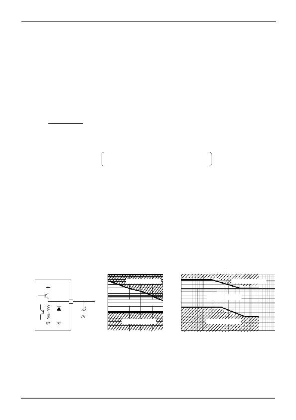
�Fig.32� Output� Equivalent� Circuit�
�Fig.33� ESR-Io� Characteristics�
�(BAxxCC0)�
�Fig.34� ESR� vs.� Io� Characteristics�
�(BAxxDD0)�
�Please� attach� an� anti-oscillation� capacitor� between� V� o� and� GND.� The� capacitance� of� the� capacitor� may� significantly� change�
�due� to� factors� such� as� temperature� changes,� making� it� impossible� to� completely� stop� oscillations.� Please� use� a� tantalum�
�capacitor� or� aluminum� electrolysis� capacitor� with� favorable� characteristics� and� small� internal� series� resistance� (ESR)� even�
�at� low� temperatures.� The� output� fluctuates� regardless� of� whether� the� ESR� is� large� or� small.� Please� use� the� IC� within� the�
�stable� operating� region� while� referring� to� the� ESR� characteristics� reference� data� shown� in� Fig.32� through� 34.� In� applications�
�where� there� are� sudden� load� fluctuations,� the� use� of� a� capacitor� with� large� capacitance� is� recommended.�
�www.rohm.com�
�?� 2013� ROHM� Co.,� Ltd.� All� rights� reserved.�
�TSZ22111� ?� 15� ?� 001�
�14/20�
�TSZ02201-0R6R0A600130-1-2�
�9.Aug.2013� Rev.003�
�相关PDF资料 |
PDF描述 |
|---|---|
| SPX2945M3-L-5-0/TR | IC REG LDO 5V .4A SOT223-3 |
| MIC5320-NDYMT TR | IC REG LDO 2.85V/1.85V 6-TMLF |
| MIC5320-LLYMT TR | IC REG LDO 2.7V .15A 6-TMLF |
| BA09CC0WFP-E2 | IC REG LDO 9V 1A TO252-5 |
| BA08CC0WFP-E2 | IC REG LDO 8V 1A TO252-5 |
相关代理商/技术参数 |
参数描述 |
|---|---|
| BAJ2CC0WT | 功能描述:低压差稳压器 - LDO REG 1A 12V RoHS:否 制造商:Texas Instruments 最大输入电压:36 V 输出电压:1.4 V to 20.5 V 回动电压(最大值):307 mV 输出电流:1 A 负载调节:0.3 % 输出端数量: 输出类型:Fixed 最大工作温度:+ 125 C 安装风格:SMD/SMT 封装 / 箱体:VQFN-20 |
| BAJ2CC0WT-V5 | 功能描述:低压差稳压器 - LDO LDO REG 12V 1A 5PIN RoHS:否 制造商:Texas Instruments 最大输入电压:36 V 输出电压:1.4 V to 20.5 V 回动电压(最大值):307 mV 输出电流:1 A 负载调节:0.3 % 输出端数量: 输出类型:Fixed 最大工作温度:+ 125 C 安装风格:SMD/SMT 封装 / 箱体:VQFN-20 |
| BAJ2DD0T | 功能描述:低压差稳压器 - LDO LDO REG 12V 2A 3PIN RoHS:否 制造商:Texas Instruments 最大输入电压:36 V 输出电压:1.4 V to 20.5 V 回动电压(最大值):307 mV 输出电流:1 A 负载调节:0.3 % 输出端数量: 输出类型:Fixed 最大工作温度:+ 125 C 安装风格:SMD/SMT 封装 / 箱体:VQFN-20 |
| BAJ2DD0WHFP | 制造商:ROHM 制造商全称:Rohm 功能描述:2A Low Dropout Voltage Regulator with Shut Down Switch |
| BAJ2DD0WHFP-TR | 功能描述:低压差稳压器 - LDO LDO REGULATOR POS 2A 6-PIN RoHS:否 制造商:Texas Instruments 最大输入电压:36 V 输出电压:1.4 V to 20.5 V 回动电压(最大值):307 mV 输出电流:1 A 负载调节:0.3 % 输出端数量: 输出类型:Fixed 最大工作温度:+ 125 C 安装风格:SMD/SMT 封装 / 箱体:VQFN-20 |
发布紧急采购,3分钟左右您将得到回复。