参数资料
| 型号: | BBT3821-JH |
| 厂商: | Intersil |
| 文件页数: | 18/75页 |
| 文件大小: | 0K |
| 描述: | IC RE-TIMER OCTAL 192-BGA |
| 标准包装: | 90 |
| 类型: | 时钟和数据恢复(CDR),多路复用器 |
| PLL: | 无 |
| 输入: | CML |
| 输出: | CML,CMOS |
| 电路数: | 1 |
| 比率 - 输入:输出: | 8:8 |
| 差分 - 输入:输出: | 是/是 |
| 频率 - 最大: | 3.1875Gbps |
| 电源电压: | 1.425 V ~ 2.5 V |
| 工作温度: | 0°C ~ 70°C |
| 安装类型: | 表面贴装 |
| 封装/外壳: | 192-EBGA |
| 供应商设备封装: | 192-EBGA-B(17x17) |
| 包装: | 托盘 |
第1页第2页第3页第4页第5页第6页第7页第8页第9页第10页第11页第12页第13页第14页第15页第16页第17页当前第18页第19页第20页第21页第22页第23页第24页第25页第26页第27页第28页第29页第30页第31页第32页第33页第34页第35页第36页第37页第38页第39页第40页第41页第42页第43页第44页第45页第46页第47页第48页第49页第50页第51页第52页第53页第54页第55页第56页第57页第58页第59页第60页第61页第62页第63页第64页第65页第66页第67页第68页第69页第70页第71页第72页第73页第74页第75页
25
Note (1): This bit should only be set if an I2C device which needs a 16-bit address is to be addressed. The NVR and DOM spaces are all 8-bit address sections, and for
these areas, this bit should be 0’b.
Note (2): Block 256-byte NVR writes will not occur unless the WRTP pin is set Low. NVR Write Page Size controls Page size for Block operations only.
Note (3): This area corresponds to the XENPAK-defined Customer Area; see XENPAK Spec R3.0 Section 10.12.22. Writes will be performed one byte at a time.
Note (4): The I2C clock speeds listed are approximate. They are derived by division from the CMU, locked to the RFCP/N inputs. At 156.25MHz, the nominal 100kHz
clock will actually be 156.25/1.6kHz, just over 97.5kHz. See also the notes to Table 117.
Note (1): These bits are latched high on any internal error condition detected. They are reset low (cleared) on being read.
Note (2): These bits are set if the EXOR sum calculated from the indicated range is not the same as the value read into the listed checksum register. Note that this is
NOT the same as the XENPAK-defined checksum calculation. Contact Intersil for a method of reconciling these two checksum calculations.
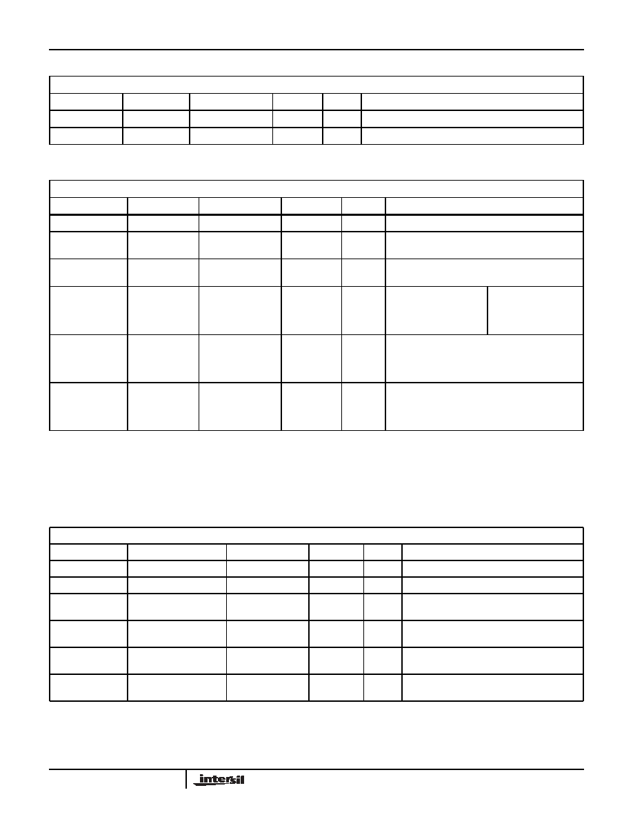
Table 19. I2C ONE-BYTE OPERATION WRITE DATA REGISTER
MDIO Register Address = 1.32772 (1.8004’h)
BIT
NAME
SETTING
DEFAULT
R/W
DESCRIPTION
1.32772.15:8
Reserved
00’h
RO
1.32772.7:0
Write Data
I2C Write Data
00’h
R/W
Data to be written by 1-byte Write Operation
Table 20. NVR I2C OPERATION CONTROL REGISTER
MDIO REGISTER ADDRESS = 1.32773 (1.8005’h)
BIT
NAME
SETTING
DEFAULT
R/W
DESCRIPTION
1.32773.15:9
Reserved
00’h
RO
1.32773.8
Long Memory(1)
1 =16 bit
0 = 8 bit
0’b
R/W
Length of address for I2C device selected
1.32773.7
NVR Write Size
0’b
R/W
1 = Block write all 256 bytes to NVR(2)
0 = Write only 1.807F:AE’h to NVR(3)
1.32773.6:4
I2C Bus Speed
Speed of I2C SCL
clock(4) (derived
from REF_CLOCK)
100’b
R/W
111 = 400kHz
110 = 200kHz
101 = 150kHz
100 = 100kHz
011 = 40kHz
010 = 20kHz
001 = 10kHz
000 = 4kHz
1.32773.3:2
NVR ACK Error
Count
11 = 63
10 = 16
01 = 4
00 = 1
11’b
R/W
Number of ACK failures at any address before I2C
Operation failure is reported
1.32773.1:0
NVR Write Page
Size(2)
11 = 32 bytes
10 = 16 bytes
01 = 8 bytes
00 = 4 byte
01’b
R/W
The I2C interface block write operation will issue a
STOP and wait for the EEPROM every time after this
number of bytes are sent out
Table 21. NVR I2C OPERATION STATUS REGISTER
MDIO REGISTER ADDRESS = 1.32774 (1.8006’h)
BIT
NAME
SETTING
DEFAULT
R/W
DESCRIPTION
1.32774.15
XP_ENA
XP_ENA pin
RO
1 = XP_ENA pin high, 0 = low
1.32774.14:4
Reserved
0000’h
RO
1.32774.3
Vendor Specific
Area EXOR sum check
Error Flag
0’b
RO LH
1 = 1.8106 ! =
EXOR(1.80AE:8105)
0 = 1.8106 =
EXOR(1.80AE:8105) (2)
1.32774.2
Customer Write Area
EXOR sum check
Error Flag
0’b
RO LH
1 = 1.80AD ! =
EXOR(1.807E:80AC)
0 = 1.80AD =
EXOR(1.807E:80AC) (2)
1.32774.1
Reserved
0’b
RO
LH(1)
1.32774.0
NVR Area EXOR sum
check
Error Flag
0’b
RO LH
1 = 1.807D ! =
EXOR(1.8007:807C)
0 = 1.807D =
EXOR(1.8007:807C) (2)
BBT3821
相关PDF资料 |
PDF描述 |
|---|---|
| VE-2NP-IW-B1 | CONVERTER MOD DC/DC 13.8V 100W |
| MS27484E12A35P | CONN PLUG 22POS STRAIGHT W/PINS |
| MAX491CSD | IC TRANS RS485/RS422 14-SOIC |
| VE-2NN-IW-B1 | CONVERTER MOD DC/DC 18.5V 100W |
| IDTQS34X245Q3G | IC BUS SWITCH 32BIT CMOS 80QVSOP |
相关代理商/技术参数 |
参数描述 |
|---|---|
| BBT3821LP-JH | 功能描述:IC RE-TIMER OCTAL 192-BGA RoHS:否 类别:集成电路 (IC) >> 时钟/计时 - 专用 系列:- 标准包装:1,500 系列:- 类型:时钟缓冲器/驱动器 PLL:是 主要目的:- 输入:- 输出:- 电路数:- 比率 - 输入:输出:- 差分 - 输入:输出:- 频率 - 最大:- 电源电压:3.3V 工作温度:0°C ~ 70°C 安装类型:表面贴装 封装/外壳:28-SSOP(0.209",5.30mm 宽) 供应商设备封装:28-SSOP 包装:带卷 (TR) 其它名称:93786AFT |
| BBTEKIT | 功能描述:剥线和切削工具 COMPR AND STRIP TOOL KIT FOR RG59 RG6 CBL RoHS:否 制造商:Molex 产品:Cable Strippers 类型: 描述/功能:Stripper |
| BB-TERM3 | 功能描述:固定接线端子 3-Position Terminal Block Breakout RoHS:否 制造商:Phoenix Contact 产品:Fixed Terminal Blocks 类型:Wire to Board 节距:5.08 mm 位置/触点数量:2 线规量程:26-16 电流额定值:13.5 A 电压额定值:250 V 安装风格:Through Hole 安装角:Straight 端接类型:Screw 触点电镀: |
| BB-TG.30.8113 | 功能描述:ANT LTE, TERMINAL 制造商:b&b smartworx, inc. 系列:- 零件状态:在售 配件类型:天线 配套使用产品/相关产品:- 标准包装:1 |
| BBU-03 | 制造商:Highpoint Technology 功能描述:BATTERY BACK UP - Bulk |
发布紧急采购,3分钟左右您将得到回复。