- 您现在的位置:买卖IC网 > PDF目录18816 > BD7411G-TR (Rohm Semiconductor)IC OMNI DETECTION 5.5V SSOP-5 PDF资料下载
参数资料
| 型号: | BD7411G-TR |
| 厂商: | Rohm Semiconductor |
| 文件页数: | 28/34页 |
| 文件大小: | 678K |
| 描述: | IC OMNI DETECTION 5.5V SSOP-5 |
| 标准包装: | 1 |
| 传感范围: | ±5.6mT 跳闸,±1.5mT 释放 |
| 类型: | 全极开关 |
| 电源电压: | 4.5 V ~ 5.5 V |
| 电流 - 电源: | 4mA |
| 电流 - 输出(最大): | ±1mA |
| 输出类型: | 数字,开路集电极 |
| 工作温度: | -40°C ~ 85°C |
| 封装/外壳: | 6-TFSOP(0.063",1.60mm 宽),5 引线 |
| 供应商设备封装: | 5-SSOP |
| 包装: | 标准包装 |
| 其它名称: | BD7411G-DKR BD7411G-DKR-ND BD7411GDKR |
第1页第2页第3页第4页第5页第6页第7页第8页第9页第10页第11页第12页第13页第14页第15页第16页第17页第18页第19页第20页第21页第22页第23页第24页第25页第26页第27页当前第28页第29页第30页第31页第32页第33页第34页
Technical Note
BU52001GUL,BU52011HFV,BU52021HFV,BU52015GUL,BU52025G,BU52053NVX,
BU52054GWZ,BU52055GWZ,BU52056NVX,BU52061NVX,BD7411G
28/31
www.rohm.com
2011.12 - Rev.G
?2011 ROHM Co., Ltd. All rights reserved.
-10
-8
-6
-4
-2
0
2
4
6
8
10
0 1 2 3 4 5 6 7 8 9 10
Horizontal distance from the magnet [mm]
Reverse
Magnetic
Field
螻otes for use
1) Absolute maximum ratings
Exceeding the absolute maximum ratings for supply voltage, operating conditions, etc. may result in damage to or
destruction of the IC. Because the source (short mode or open mode) cannot be identified if the device is damaged in this
way, it is important to take physical safety measures such as fusing when implementing any special mode that operates in
excess of absolute rating limits.
2) GND voltage
Make sure that the GND terminal potential is maintained at the minimum in any operating state, and is always kept lower
than the potential of all other pins.
3) Thermal design
Use a thermal design that allows for sufficient margin in light of the power dissipation (Pd) in actual operating conditions.
4) Pin shorts and mounting errors
Use caution when positioning the IC for mounting on printed circuit boards. Mounting errors, such as improper positioning
or orientation, may damage or destroy the device. The IC may also be damaged or destroyed if output pins are shorted
together, or if shorts occur between the output pin and supply pin or GND.
5) Positioning components in proximity to the Hall IC and magnet
Positioning magnetic components in close proximity to the Hall IC or magnet may alter the magnetic field, and therefore
the magnetic detection operation. Thus, placing magnetic components near the Hall IC and magnet should be avoided in
the design if possible. However, where there is no alternative to employing such a design, be sure to thoroughly test and
evaluate performance with the magnetic component(s) in place to verify normal operation before implementing the design.
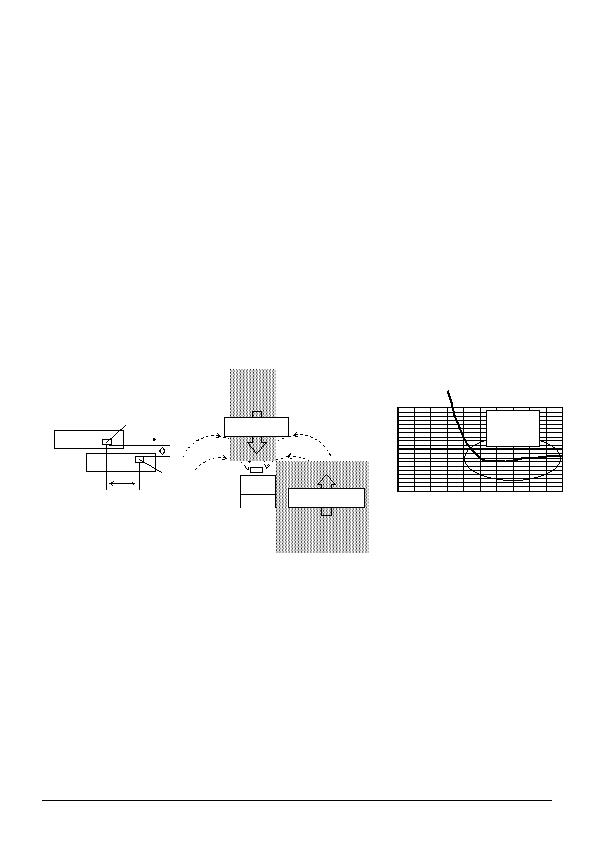
6) Slide-by position sensing
Fig.73 depicts the slide-by configuration employed for position sensing. Note that when the gap (d) between the magnet
and the Hall IC is narrowed, the reverse magnetic field generated by the magnet can cause the IC to malfunction. As seen
in Fig.74, the magnetic field runs in opposite directions at Point A and Point B. Since the bipolar detection Hall IC can
detect the S-pole at Point A and the N-pole at Point B, it can wind up switching output ON as the magnet slides by in the
process of position detection. Fig. 75 plots magnetic flux density during the magnet slide-by. Although a reverse magnetic
field was generated in the process, the magnetic flux density decreased compared with the center of the magnet. This
demonstrates that slightly widening the gap (d) between the magnet and Hall IC reduces the reverse magnetic field and
prevents malfunctions.
7) Operation in strong electromagnetic fields
Exercise extreme caution about using the device in the presence of a strong electromagnetic field, as such use may cause
the IC to malfunction.
8) Common impedance
Make sure that the power supply and GND wiring limits common impedance to the extent possible by, for example,
employing short, thick supply and ground lines. Also, take measures to minimize ripple such as using an inductor or
capacitor.
9) GND wiring pattern
When both a small-signal GND and high-current GND are provided, single-point grounding at the reference point of the set
PCB is recommended, in order to separate the small-signal and high-current patterns, and to ensure that voltage changes
due to the wiring resistance and high current do not cause any voltage fluctuation in the small-signal GND. In the same
way, care must also be taken to avoid wiring pattern fluctuations in the GND wiring pattern of external components.
10) Exposure to strong light
Exposure to halogen lamps, UV and other strong light sources may cause the IC to malfunction. If the IC is subject to such
exposure, provide a shield or take other measures to protect it from the light. In testing, exposure to white LED and
fluorescent light sources was shown to have no significant effect on the IC.
11) Power source design
Since the IC performs intermittent operation, it has peak current when its ON. Please taking that into account and under
examine adequate evaluations when designing the power source.
L
Magnet
Hall IC
Slide
Fig.73
Fig.75
Fig.74
B
S
A
N
Magnetic Flux
Magnetic Flux
相关PDF资料 |
PDF描述 |
|---|---|
| TA20161803DH | SCR PHASE CTRL 1600V 1800A |
| TAK7361202DH | SCR PHASE CTRL 3600V 1200A |
| 633W-60 YEL | LEAD TEST MINIHK-RA BANAPLG YEL |
| TA20141803DH | SCR PHASE CTRL 1400V 1800A |
| 7W-36.000MBA-T | OSC 36.000 MHZ 3.3V SMT |
相关代理商/技术参数 |
参数描述 |
|---|---|
| BD7411GUL-E2 | 制造商:ROHM 制造商全称:Rohm 功能描述:Omnipolar Detection Hall ICs |
| BD7411GUL-TR | 制造商:ROHM 制造商全称:Rohm 功能描述:Omnipolar Detection Hall ICs |
| BD7411HFV-E2 | 制造商:ROHM 制造商全称:Rohm 功能描述:Omnipolar Detection Hall ICs |
| BD7411HFV-TR | 制造商:ROHM 制造商全称:Rohm 功能描述:Omnipolar Detection Hall ICs |
| BD7411NVX-E2 | 制造商:ROHM 制造商全称:Rohm 功能描述:Omnipolar Detection Hall ICs |
发布紧急采购,3分钟左右您将得到回复。