- 您现在的位置:买卖IC网 > PDF目录17908 > BK32164L121-T (Taiyo Yuden)FERRITE BEAD ARRAY 120OHMS 1206 PDF资料下载
参数资料
| 型号: | BK32164L121-T |
| 厂商: | Taiyo Yuden |
| 文件页数: | 30/31页 |
| 文件大小: | 0K |
| 描述: | FERRITE BEAD ARRAY 120OHMS 1206 |
| 标准包装: | 1 |
| 系列: | BK |
| 频率对应阻抗: | 120 欧姆 @ 100MHz |
| 额定电流: | 200mA |
| DC 电阻(DCR): | 最大 550 毫欧 |
| 滤波器类型: | 差模 - 4 线阵列 |
| 封装/外壳: | 1206(3216 公制),阵列,8 PC 板 |
| 安装类型: | 表面贴装 |
| 包装: | 标准包装 |
| 高度(最大): | 0.035"(0.90mm) |
| 尺寸/尺寸: | 0.126" L x 0.063" W(3.20mm x 1.60mm) |
| 其它名称: | 587-2684-6 |
第1页第2页第3页第4页第5页第6页第7页第8页第9页第10页第11页第12页第13页第14页第15页第16页第17页第18页第19页第20页第21页第22页第23页第24页第25页第26页第27页第28页第29页当前第30页第31页
�� �
�
�◆Selection� of� Flux�
�1-1.� When� too� much� halogenated� substance(Chlorine,� etc.)content� is� used� to� activate� the� flux,� or� highly� acidic� flux� is� used,� an� excessive�
�amount� of� residue� after� soldering� may� lead� to� corrosion� of� the� terminal� electrodes� or� degradation� of� insulation� resistance� on� the�
�surface� of� the� Inductor.�
�1-2.� Flux� is� used� to� increase� solderability� in� flow� soldering,� but� if� too� much� is� applied,� a� large� amount� of� flux� gas� may� be� emitted� and� may�
�detrimentally� affect� solderability.� To� minimize� the� amount� of� flux� applied,� it� is� recommended� to� use� a� flux-bubbling� system.�
�1-3.� Since� the� residue� of� water-soluble� flux� is� easily� dissolved� by� water� content� in� the� air,� the� residue� on� the� surface� of� Inductor� in� high�
�humidity� conditions� may� cause� a� degradation� of� insulation� resistance� and� therefore� affect� the� reliability� of� the� components.� The�
�cleaning� methods� and� the� capability� of� the� machines� used� should� also� be� considered� carefully� when� selecting� water-soluble� flux.�
�◆Soldering�
�1-1.� Preheating� when� soldering�
�Heating:� Chip� inductor� components� should� be� preheated� to� within� 100� to� 130℃� of� the� soldering.� Cooling:� The� temperature� difference�
�between� the� components� and� cleaning� process� should� not� be� greater� than� 100℃.�
�Chip� inductors� are� susceptible� to� thermal� shock� when� exposed� to� rapid� or� concentrated� heating� or� rapid� cooling.� Therefore,� the�
�soldering� process� must� be� conducted� with� a� great� care� so� as� to� prevent� malfunction� of� the� components� due� to� excessive� thermal�
�shock.�
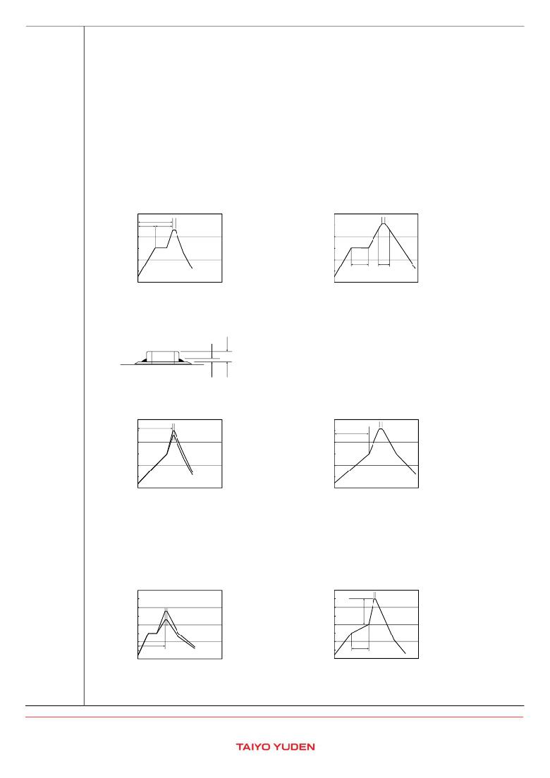
�Recommended� conditions� for� soldering� Pb� free� soldering�
�[Reflow� soldering]�
�Temperature� profile�
�300�
�Preheating�
�60sec.� 60sec�
�230℃�
�Within� 10sec.�
�300�
�Peak�
�260℃� Max.�
�Within� 10sec.�
�200�
�Min.�
�Min.�
�Slow� cooling�
�200�
�Slow�
�cooling�
�100�
�100�
�Preheating150℃� Heating� above�
�60sec.� Min.�
�230℃�
�0�
�0�
�40sec.� Max.�
�※Ceramic� chip� components� should� be� preheated� to� within� 100� to� 130℃� of� the�
�soldering.�
�※Assured� to� be� reflow� soldering� for� 2� times.�
�Caution�
�1.� The� ideal� condition� is� to� have� solder� mass(fillet)controlled� to� 1/2� to� 1/3� of� the� thickness� of� the� inductor,� as� shown�
�below:�
�1/2T~1/3T�
�Inductor�
�Technical�
�considerations�
�Solder�
�PC� board�
�T�
�2.� Because� excessive� dwell� times� can� detrimentally� affect� solderability,� soldering� duration� should� be� kept� as� close� to�
�recommended� times� as� possible.�
�[Wave� soldering]�
�Temperature� profile�
�300�
�200�
�Preheating�
�120sec.� Min.�
�230~250℃�
�Within� 3sec.�
�300�
�200�
�120sec.� Min.�
�Peak�
�260℃� Max.�
�Within� 10sec.�
�Slow� cooling�
�Preheating�
�Slow�
�cooling�
�100�
�0�
�100�
�0�
�150℃�
�※Ceramic� chip� components� should� be� preheated� to� within� 100� to� 130℃� of� the�
�soldering.�
�※Assured� to� be� wave� soldering� for� 1� time.�
�※Except� for� reflow� soldering� type.�
�Caution�
�1.� Make� sure� the� inductors� are� preheated� sufficiently.�
�2.� The� temperature� difference� between� the� inductor� and� melted� solder� should� not� be� greater� than� 100� to� 130℃.�
�3.� Cooling� after� soldering� should� be� as� gradual� as� possible.�
�4.� Wave� soldering� must� not� be� applied� to� the� inductors� designated� as� for� reflow� soldering� only.�
�[Hand� soldering]�
�Temperature� profile�
�400�
�300�
�230~280℃�
�Within� 3sec.�
�400�
�300�
�Peak�
�350℃� Max.�
�Within� 3sec.�
�⊿T�
�Slow� cooling�
�200�
�Slow� cooling�
�200�
�Preheating�
�100�
�Preheating�
�100�
�150℃� Min.�
�0�
�60sec.� Min.�
�0�
�60sec.� Min.�
�(※⊿T≦190℃(� 3216Type� max),� ⊿T≦130℃(� 3225� Type� min)�
�※It� is� recommended� to� use� 20W� soldering� iron� and� the� tip� is� 1φ� or� less.�
�※The� soldering� iron� should� not� directly� touch� the� components.�
�※Assured� to� be� soldering� iron� for� 1� time.�
�Note:� The� above� profiles� are� the� maximum� allowable� soldering� condition,� therefore�
�these� profiles� are� not� always� recommended.�
�?� This� catalog� contains� the� typical� specification� only� due� to� the� limitation� of� space.� When� you� consider� the� purchase� of� our� products,� please� check� our� specification.�
�For� details� of� each� product� (characteristics� graph,� reliability� information,� precautions� for� use,� and� so� on),� see� our� Web� site� (http://www.ty-top.com/)� .�
�i_mlci_prec_e-E02R01�
�相关PDF资料 |
PDF描述 |
|---|---|
| MCM01-010ED561G-F | CAP MICA 560PF 500V 2% SMD |
| 942C6W1K | CAP FILM 1UF 600VDC AXIAL |
| 3386W-1-102LF | TRIMMER 1K OHM 0.5W TH |
| MCM01-010ED511G-F | CAP MICA 510PF 500V 2% SMD |
| 3386P-1-205LF | TRIMMER 2M OHM 0.5W TH |
相关代理商/技术参数 |
参数描述 |
|---|---|
| BK32164L181-T | 功能描述:电磁干扰滤波珠子、扼流圈和阵列 FER BD CHIP ARRAY 1206 180OHMS 25% RoHS:否 制造商:AVX 阻抗: 最大直流电流:35 mA 最大直流电阻: 容差: 端接类型:SMD/SMT 电压额定值:25 V 工作温度范围:- 25 C to + 85 C 封装 / 箱体:0603 (1608 metric) |
| BK32164L241-T | 功能描述:电磁干扰滤波珠子、扼流圈和阵列 FER BD CHIP ARRAY 1206 240OHMS 25% RoHS:否 制造商:AVX 阻抗: 最大直流电流:35 mA 最大直流电阻: 容差: 端接类型:SMD/SMT 电压额定值:25 V 工作温度范围:- 25 C to + 85 C 封装 / 箱体:0603 (1608 metric) |
| BK32164L680-T | 功能描述:电磁干扰滤波珠子、扼流圈和阵列 FER BD CHIP ARRAY 1206 68OHMS 25% RoHS:否 制造商:AVX 阻抗: 最大直流电流:35 mA 最大直流电阻: 容差: 端接类型:SMD/SMT 电压额定值:25 V 工作温度范围:- 25 C to + 85 C 封装 / 箱体:0603 (1608 metric) |
| BK32164M102-T | 功能描述:电磁干扰滤波珠子、扼流圈和阵列 FER BD CHIP ARRAY 1206 1000OHMS 25% RoHS:否 制造商:AVX 阻抗: 最大直流电流:35 mA 最大直流电阻: 容差: 端接类型:SMD/SMT 电压额定值:25 V 工作温度范围:- 25 C to + 85 C 封装 / 箱体:0603 (1608 metric) |
| BK32164M121-T | 功能描述:电磁干扰滤波珠子、扼流圈和阵列 FER BD CHIP ARRAY 1206 120OHMS 25% RoHS:否 制造商:AVX 阻抗: 最大直流电流:35 mA 最大直流电阻: 容差: 端接类型:SMD/SMT 电压额定值:25 V 工作温度范围:- 25 C to + 85 C 封装 / 箱体:0603 (1608 metric) |
发布紧急采购,3分钟左右您将得到回复。