- 您现在的位置:买卖IC网 > PDF目录375623 > C440C569J5G5HA (KEMET Corporation) Ceramic Leaded Capacitors PDF资料下载
参数资料
| 型号: | C440C569J5G5HA |
| 厂商: | KEMET Corporation |
| 英文描述: | Ceramic Leaded Capacitors |
| 中文描述: | 引线陶瓷电容器 |
| 文件页数: | 44/48页 |
| 文件大小: | 682K |
| 代理商: | C440C569J5G5HA |
第1页第2页第3页第4页第5页第6页第7页第8页第9页第10页第11页第12页第13页第14页第15页第16页第17页第18页第19页第20页第21页第22页第23页第24页第25页第26页第27页第28页第29页第30页第31页第32页第33页第34页第35页第36页第37页第38页第39页第40页第41页第42页第43页当前第44页第45页第46页第47页第48页

APPLICATION NOTES FOR MULTILAYER CERAMIC CAPACITORS
KEMET Electronics Corporation, P.O. Box 5928, Greenville, S.C. 29606, (864) 963-6300
44
Effect of Temperature:
Both capacitance and dissipa-
tion factor are affected by variations in temperature. The max-
imum capacitance change with temperature is defined by the
temperature characteristic. However, this only defines a “box”
bounded by the upper and lower operating temperatures and
the minimum and maximum capacitance values. Within this
“box”, the variation with temperature depends upon the spe-
cific dielectric formulation. Typical curves for KEMET capaci-
tors are shown in Figures 3, 4, and 5. These figures also
include the typical change in dissipation factor for KEMET
capacitors.
Insulation resistance decreases with temperature.
Typically, the insulation resistance at maximum rated temper-
ature is 10% of the 25°C value.
Effect of Voltage:
Class I ceramic capacitors are not
affected by variations in applied AC or DC voltages. For Class
II and III ceramic capacitors, variations in voltage affect only
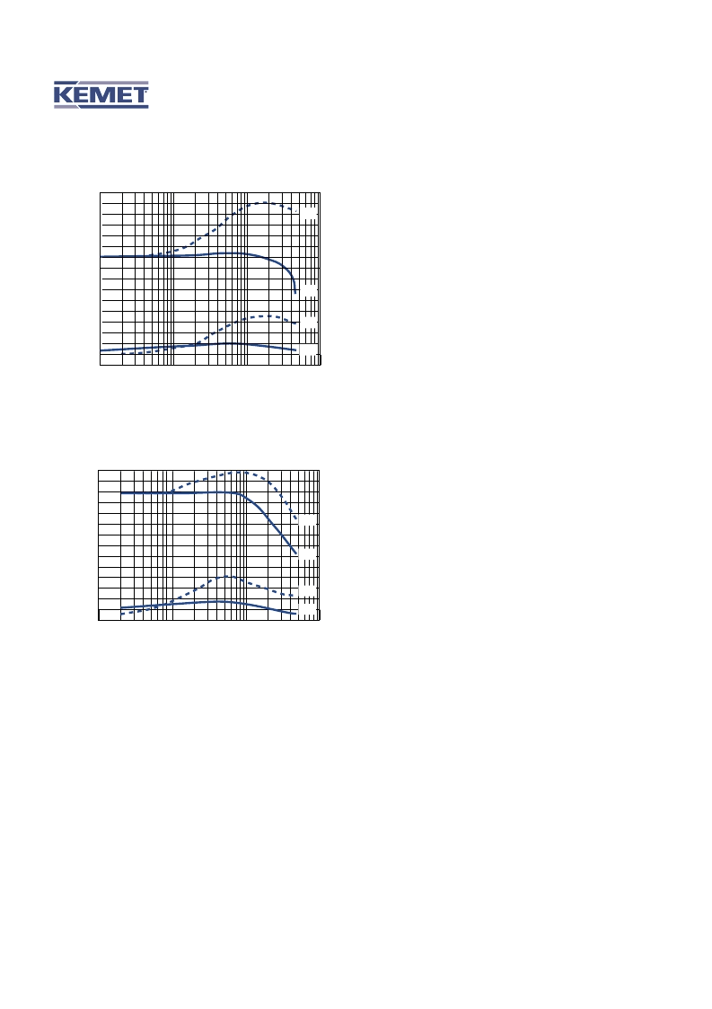
EFFECT OF APPLIED VOLTAGE
0.1
1
10
100
AC or DC Volts Applied
Typical Effects of 1000 Hz AC and DC Voltage Level on
Capacitance and Dissipation Factor - Z5U
Note: C0G Dielectric capacitance and dissipation factor are
stable with voltage.
Figure 7.
1
2
3
4
+20
0
-20
-40
-60
1
2
3
4
+10
+5
0
-5
-10
0.1
1
10
100
AC or DC Volts Applied
Typical Effects of 1000 Hz AC and DC Voltage Level on
Capacitance and Dissipation Factor - X7R
Note: C0G Dielectric capacitance and dissipation factor are
stable with voltage.
Figure 6.
DC
AC
AC
DC
%
%
%
%
DC
AC
AC
DC
the capacitance and dissipation factor. The application of DC
voltage higher than 5 vdc reduces both the capacitance and
dissipation factor. The application of AC voltages up to 10-20
Vac tends to increase both capacitance and dissipation factor.
At higher AC voltages, both capacitance and dissipation factor
begin to decrease.
Typical curves showing the effect of applied AC and DC
voltage are shown in Figure 6 for KEMET X7R capacitors and
Figure 7 for KEMET Z5U capacitors.
Effect of Frequency:
Frequency affects both capaci-
tance and dissipation factor. Typical curves for KEMET multi-
layer ceramic capacitors are shown in Figures 8 and 9.
T
he variation of impedance with frequency is an impor-
tant consideration in the application of multilayer ceramic
capacitors. Total impedance of the capacitor is the vector of the
capacitive reactance, the inductive reactance, and the ESR, as
illustrated in Figure 2. As frequency increases, the capacitive
reactance decreases. However, the series inductance (L)
shown in Figure 1 produces inductive reactance, which
increases with frequency. At some frequency, the impedance
ceases to be capacitive and becomes inductive. This point, at
the bottom of the V-shaped impedance versus frequency
curves, is the self-resonant frequency. At the self-resonant fre-
quency, the reactance is zero, and the impedance consists of
the ESR only.
Typical impedance versus frequency curves for KEMET
multilayer ceramic capacitors are shown in Figures 10, 11, and
12. These curves apply to KEMET capacitors in chip form, with-
out leads. Lead configuration and lead length have a significant
impact on the series inductance. The lead inductance is
approximately 10nH/inch, which is large compared to the
inductance of the chip. The effect of this additional inductance
is a decrease in the self-resonant frequency, and an increase
in impedance in the inductive region above the self-resonant
frequency.
Effect of Time:
The capacitance of Class II and III
dielectrics change with time as well as with temperature, volt-
age and frequency. This change with time is known as “aging.”
It is caused by gradual realignment of the crystalline structure
of the ceramic dielectric material as it is cooled below its Curie
temperature, which produces a loss of capacitance with time.
The aging process is predictable and follows a logarithmic
decay. Typical aging rates for C0G, X7R, and Z5U dielectrics
are as follows:
C0G
X7R
Z5U
None
2.0% per decade of time
5.0% per decade of time
Typical aging curves for X7R and Z5U dielectrics are
shown in Figure 13.
The aging process is reversible. If the capacitor is heat-
ed to a temperature above its Curie point for some period of
time, de-aging will occur and the capacitor will regain the
capacitance lost during the aging process. The amount of de-
aging depends on both the elevated temperature and the
length of time at that temperature. Exposure to 150°C for one-
half hour or 125°C for two hours is usually sufficient to return
the capacitor to its initial value.
Because the capacitance changes rapidly immediately
after de-aging, capacitance measurements are usually delayed
for at least 10 hours after the de-aging process, which is often
referred to as the “last heat.” In addition, manufacturers utilize
相关PDF资料 |
PDF描述 |
|---|---|
| C440C569J5G5TA | Ceramic Leaded Capacitors |
| C440C569J5R5CA | Ceramic Leaded Capacitors |
| C440C569J5R5HA | Ceramic Leaded Capacitors |
| C440C569J5R5TA | Ceramic Leaded Capacitors |
| C440C569J5U5CA | Ceramic Leaded Capacitors |
相关代理商/技术参数 |
参数描述 |
|---|---|
| C440C569J5G5TA | 制造商:KEMET 制造商全称:Kemet Corporation 功能描述:Ceramic Leaded Capacitors |
| C440C569J5R5CA | 制造商:KEMET 制造商全称:Kemet Corporation 功能描述:Ceramic Leaded Capacitors |
| C440C569J5R5HA | 制造商:KEMET 制造商全称:Kemet Corporation 功能描述:Ceramic Leaded Capacitors |
| C440C569J5R5TA | 制造商:KEMET 制造商全称:Kemet Corporation 功能描述:Ceramic Leaded Capacitors |
| C440C569J5U5CA | 制造商:KEMET 制造商全称:Kemet Corporation 功能描述:Ceramic Leaded Capacitors |
发布紧急采购,3分钟左右您将得到回复。