- 您现在的位置:买卖IC网 > PDF目录366625 > C8051F310 (Electronic Theatre Controls, Inc.) 8/16 kB ISP Flash MCU Family PDF资料下载
参数资料
| 型号: | C8051F310 |
| 厂商: | Electronic Theatre Controls, Inc. |
| 英文描述: | 8/16 kB ISP Flash MCU Family |
| 中文描述: | 8 / 16 kB的ISP闪存微控制器系列 |
| 文件页数: | 1/310页 |
| 文件大小: | 2478K |
| 代理商: | C8051F310 |
当前第1页第2页第3页第4页第5页第6页第7页第8页第9页第10页第11页第12页第13页第14页第15页第16页第17页第18页第19页第20页第21页第22页第23页第24页第25页第26页第27页第28页第29页第30页第31页第32页第33页第34页第35页第36页第37页第38页第39页第40页第41页第42页第43页第44页第45页第46页第47页第48页第49页第50页第51页第52页第53页第54页第55页第56页第57页第58页第59页第60页第61页第62页第63页第64页第65页第66页第67页第68页第69页第70页第71页第72页第73页第74页第75页第76页第77页第78页第79页第80页第81页第82页第83页第84页第85页第86页第87页第88页第89页第90页第91页第92页第93页第94页第95页第96页第97页第98页第99页第100页第101页第102页第103页第104页第105页第106页第107页第108页第109页第110页第111页第112页第113页第114页第115页第116页第117页第118页第119页第120页第121页第122页第123页第124页第125页第126页第127页第128页第129页第130页第131页第132页第133页第134页第135页第136页第137页第138页第139页第140页第141页第142页第143页第144页第145页第146页第147页第148页第149页第150页第151页第152页第153页第154页第155页第156页第157页第158页第159页第160页第161页第162页第163页第164页第165页第166页第167页第168页第169页第170页第171页第172页第173页第174页第175页第176页第177页第178页第179页第180页第181页第182页第183页第184页第185页第186页第187页第188页第189页第190页第191页第192页第193页第194页第195页第196页第197页第198页第199页第200页第201页第202页第203页第204页第205页第206页第207页第208页第209页第210页第211页第212页第213页第214页第215页第216页第217页第218页第219页第220页第221页第222页第223页第224页第225页第226页第227页第228页第229页第230页第231页第232页第233页第234页第235页第236页第237页第238页第239页第240页第241页第242页第243页第244页第245页第246页第247页第248页第249页第250页第251页第252页第253页第254页第255页第256页第257页第258页第259页第260页第261页第262页第263页第264页第265页第266页第267页第268页第269页第270页第271页第272页第273页第274页第275页第276页第277页第278页第279页第280页第281页第282页第283页第284页第285页第286页第287页第288页第289页第290页第291页第292页第293页第294页第295页第296页第297页第298页第299页第300页第301页第302页第303页第304页第305页第306页第307页第308页第309页第310页
Page 1
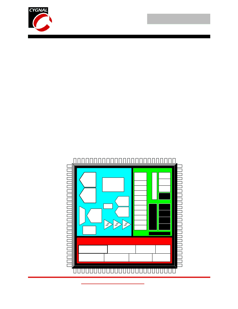
Mixed-Signal ISP FLASH MCU Family
C8051F060/1/2/3
A
DVANCD
NORMAION
DEBUG
CIRCUITRY
INTERRUPTS
Advanced
Information
ANALOG PERIPHERALS
-
Two 16-Bit SAR ADCs
16-Bit Resolution
±0.75 LSB INL, guaranteed no missing codes
Programmable Throughput up to 1 Msps
Operate as Two Single-Ended or One Differential Con-
verter
Direct Memory Access; Data Stored in RAM Without Soft-
ware Overhead
Data-Dependent Windowed Interrupt Generator
-
10-bit SAR ADC
Programmable Throughput up to 200 ksps
8 External Inputs, Single-Ended or Differential
Built-in Temperature Sensor
-
Two 12-bit DACs
Can Synchronize Outputs to Timers for Jitter-Free Wave-
form Generation
-
Three Analog Comparators
Programmable Hysteresis/Response Time
-
Voltage Reference
-
Precision VDD Monitor/Brown-Out Detector
ON-CHIP JTAG DEBUG & BOUNDARY SCAN
-
On-Chip Debug Circuitry Facilitates Full- Speed, Non-
Intrusive In-Circuit/In-System Debugging
-
Provides Breakpoints, Single-Stepping, Watchpoints,
Stack Monitor; Inspect/Modify Memory and Registers
-
Superior Performance to Emulation Systems Using ICE-
Chips, Target Pods, and Sockets
-
IEEE1149.1 Compliant Boundary Scan
-
Complete Development Kit
HIGH SPEED 8051
μ
C CORE
Instruction Set in 1 or 2 System Clocks
-
Up to 25 MIPS Throughput with 25 MHz Clock
-
Flexible Interrupt Sources
MEMORY
-
4352 Bytes Internal Data RAM (4k + 256)
-
64k Bytes FLASH; In-System programmable in 512-byte
Sectors
-
External 64k Byte Data Memory Interface with multi-
plexed and non-multiplexed modes (C8051F060/2)
DIGITAL PERIPHERALS
-
59 General Purpose I/O Pins (C8051F060/2)
-
24 General Purpose I/O Pins (C8051F061/3)
-
Bosch Controller Area Network (CAN 2.0B), Hardware
SMBus (I
2
C Compatible), SPI, and Two UART
Serial Ports Available Concurrently
-
Programmable 16-bit Counter/Timer Array with
6 Capture/Compare Modules
-
5 General Purpose 16-bit Counter/Timers
-
Dedicated Watch-Dog Timer; Bi-directional Reset Pin
CLOCK SOURCES
-
Internal Calibrated Precision Oscillator: 24.5 MHz
-
External Oscillator: Crystal, RC, C, or Clock
-
Real-Time Clock Mode using Timer 2, 3, 4, or PCA
SUPPLY VOLTAGE .......................... 2.7V TO 3.6V
-
Multiple Power Saving Sleep and Shutdown Modes
100-Pin TQFP and 64-Pin TQFP Packages Available
Temperature Range: -40°C to +85°C
JTAG
64KB
ISP FLASH
4352 B
SRAM
SANITY
CONTROL
16-bit
1 Msps
ADC
CLOCK
CIRCUIT
TEMP
SENSOR
ANALOG PERIPHERALS
Port 0
Port 1
Port 2
C
DIGITAL I/O
CAN
2.0B
8051 CPU
(25MIPS)
22
10-bit
200ksps
ADC
Port 4
Port 5
Port 6
Port 7
E
I
100 pin Only
UART0
SMBus
SPI Bus
PCA
Timer 0
Timer 1
Timer 2
Timer 3
Timer 4
UART1
VREF
DMA
Interface
16-bit
1 Msps
ADC
12-Bit
DAC
VOLTAGE
COMPARATORS
+
-
+
-
+
-
12-Bit
DAC
Port 3
相关PDF资料 |
PDF描述 |
|---|---|
| C8051F310-GQ | 8/16 kB ISP Flash MCU Family |
| C8051F317 | 8/16 kB ISP Flash MCU Family |
| C8051F317-GM | 8/16 kB ISP Flash MCU Family |
| C8051F300DK | Mixed Signal ISP Flash MCU Family |
| C8051F300 | Mixed Signal ISP Flash MCU Family |
相关代理商/技术参数 |
参数描述 |
|---|---|
| C8051F310_1 | 制造商:SILABS 制造商全称:SILABS 功能描述:8/16 kB ISP Flash MCU Family |
| C8051F310DK | 功能描述:开发板和工具包 - 8051 MCU DEVELOPMENT KIT W/ US POWER SUPPLY RoHS:否 制造商:Silicon Labs 产品:Development Kits 工具用于评估:C8051F960, Si7005 核心: 接口类型:USB 工作电源电压: |
| C8051F310DK-A | 功能描述:DEV KIT FOR C8051F310/F311 RoHS:否 类别:编程器,开发系统 >> 过时/停产零件编号 系列:- 标准包装:1 系列:- 类型:MCU 适用于相关产品:Freescale MC68HC908LJ/LK(80-QFP ZIF 插口) 所含物品:面板、缆线、软件、数据表和用户手册 其它名称:520-1035 |
| C8051F310DK-B | 功能描述:DEV KIT FOR C8051F310/F311 RoHS:否 类别:编程器,开发系统 >> 过时/停产零件编号 系列:- 标准包装:1 系列:- 类型:MCU 适用于相关产品:Freescale MC68HC908LJ/LK(80-QFP ZIF 插口) 所含物品:面板、缆线、软件、数据表和用户手册 其它名称:520-1035 |
| C8051F310DK-E | 功能描述:DEV KIT FOR C8051F310/F311 RoHS:否 类别:编程器,开发系统 >> 过时/停产零件编号 系列:- 标准包装:1 系列:- 类型:MCU 适用于相关产品:Freescale MC68HC908LJ/LK(80-QFP ZIF 插口) 所含物品:面板、缆线、软件、数据表和用户手册 其它名称:520-1035 |
发布紧急采购,3分钟左右您将得到回复。