参数资料
| 型号: | CAT9555HV6I-G |
| 厂商: | ON Semiconductor |
| 文件页数: | 15/16页 |
| 文件大小: | 0K |
| 描述: | IC I/O EXPANDER 16BI 2C 24TQFN |
| 标准包装: | 92 |
| 接口: | I²C,串行,SMBus |
| 输入/输出数: | 16 |
| 中断输出: | 是 |
| 频率 - 时钟: | 400kHz |
| 电源电压: | 2.3 V ~ 5.5 V |
| 工作温度: | -40°C ~ 85°C |
| 安装类型: | 表面贴装 |
| 封装/外壳: | 24-WFQFN 裸露焊盘 |
| 供应商设备封装: | 24-TQFN(4x4) |
| 包装: | 管件 |
| 包括: | POR |
CAT9555
http://onsemi.com
8
FUNCTIONAL DESCRIPTION
The CAT9555 general purpose input/output (GPIO)
peripheral provides up to sixteen I/O ports, controlled
through an I2C compatible serial interface.
The CAT9555 supports the I2C Bus data transmission
protocol. This InterIntegrated Circuit Bus protocol defines
any device that sends data to the bus to be a transmitter and
any device receiving data to be a receiver. The transfer is
controlled by the Master device which generates the serial
clock and all START and STOP conditions for bus access.
The CAT9555 operates as a Slave device. Both the Master
device and Slave device can operate as either transmitter or
receiver, but the Master device controls which mode is
activated.
I2C Bus Protocol
The features of the I2C bus protocol are defined as follows:
1. Data transfer may be initiated only when the bus is
not busy.
2. During a data transfer, the data line must remain
stable whenever the clock line is high. Any
changes in the data line while the clock line is high
will be interpreted as a START or STOP condition
(Figure 7).
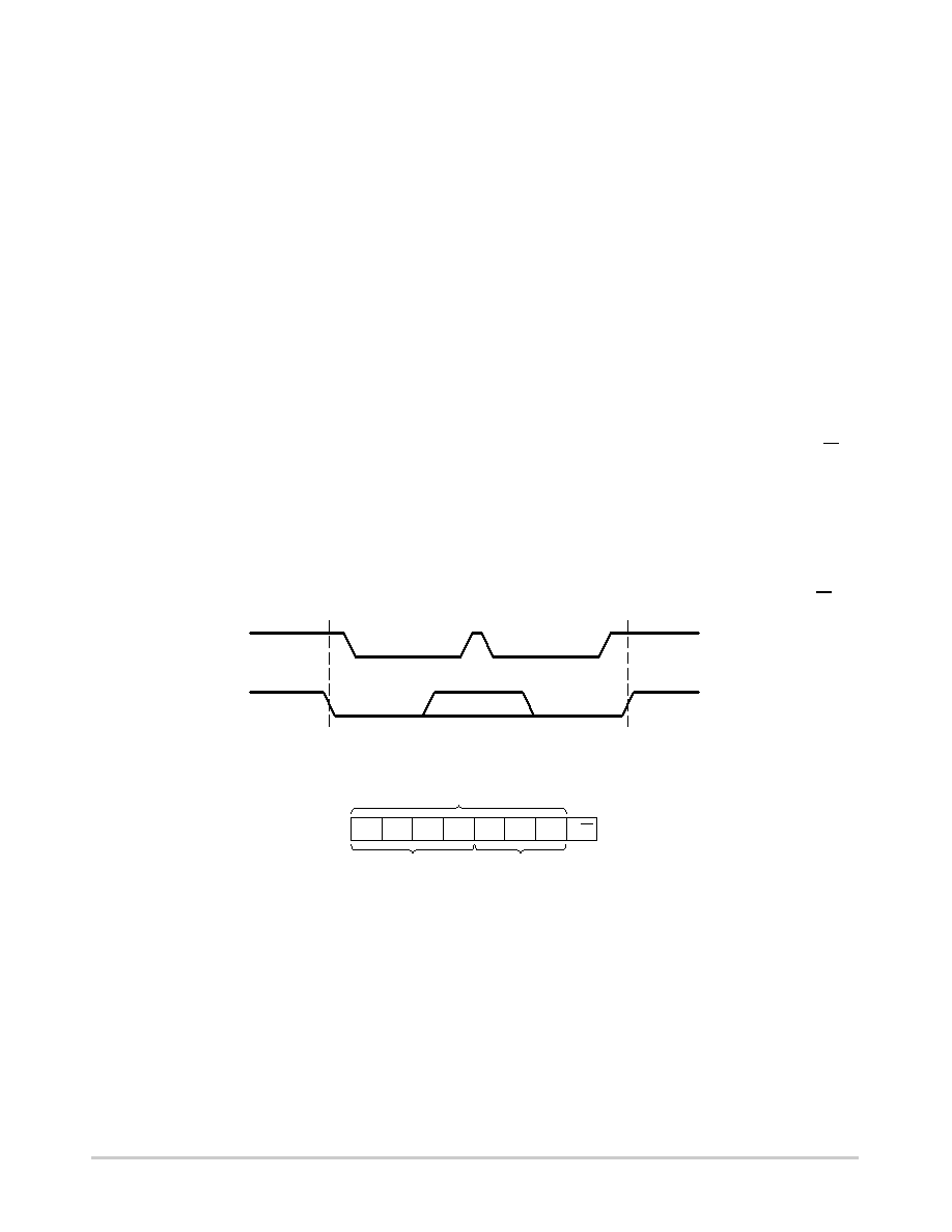
START and STOP Conditions
The START Condition precedes all commands to the
device, and is defined as a HIGH to LOW transition of SDA
when SCL is HIGH. The CAT9555 monitors the SDA and
SCL lines and will not respond until this condition is met.
A LOW to HIGH transition of SDA when SCL is HIGH
determines the STOP condition. All operations must end
with a STOP condition.
Device Addressing
After the bus Master sends a START condition, a slave
address byte is required to enable the CAT9555 for a read or
write operation. The four most significant bits of the slave
address are fixed as binary 0100 (Figure 8). The CAT9555
uses the next three bits as address bits.
The address bits A2, A1 and A0 are used to select which
device is accessed from maximum eight devices on the same
bus. These bits must compare to their hardwired input pins.
The 8th bit following the 7bit slave address is the R/W bit
that specifies whether a read or write operation is to be
performed. When this bit is set to “1”, a read operation is
initiated, and when set to “0”, a write operation is selected.
Following the START condition and the slave address byte,
the CAT9555 monitors the bus and responds with an
acknowledge (on the SDA line) when its address matches the
transmitted slave address. The CAT9555 then performs a read
or a write operation depending on the state of the R/W bit.
Figure 7. START/STOP Condition
Figure 8. CAT9555 Slave Address
0
10
0
A2
A1 A0
SLAVE ADDRESS
FIXED
PROGRAMMABLE
HARDWARE SELECTABLE
R/W
START CONDITION
STOP CONDITION
SDA
SCL
Acknowledge
After a successful data transfer, each receiving device is
required to generate an acknowledge. The acknowledging
device pulls down the SDA line during the ninth clock cycle,
signaling that it received the 8 bits of data. The SDA line
remains stable LOW during the HIGH period of the
acknowledge related clock pulse (Figure 9).
The CAT9555 responds with an acknowledge after
receiving a START condition and its slave address. If the
device has been selected along with a write operation, it
responds with an acknowledge after receiving each data byte.
When the CAT9555 begins a READ mode it transmits 8
bits of data, releases the SDA line, and monitors the line for
an acknowledge. Once it receives this acknowledge, the
CAT9555 will continue to transmit data. If no acknowledge
is sent by the Master, the device terminates data transmission
and waits for a STOP condition. The master must then issue
a stop condition to return the CAT9555 to the standby power
mode and place the device in a known state.
相关PDF资料 |
PDF描述 |
|---|---|
| CC-2401K2A-CS | MODEM 2400BAUD SECURE 3.3V |
| CC-2434K2-CS5 | MODEM FAX 33K 5V |
| CC-24K2N-CS5 | MODEM WORLD NET 2400BAUD 5V |
| CC-92K2-IS | MODEM 56KBAUD V.90 SERIAL 3.3V |
| CC-MX-LB69-ZM | CONNECTCORE I.MX51 MODULE |
相关代理商/技术参数 |
参数描述 |
|---|---|
| CAT9555HV6I-GT2 | 功能描述:接口-I/O扩展器 I2C/SMBUS Expander 16B,w/Int RoHS:否 制造商:NXP Semiconductors 逻辑系列: 输入/输出端数量: 最大工作频率:100 kHz 工作电源电压:1.65 V to 5.5 V 工作温度范围:- 40 C to + 85 C 安装风格:SMD/SMT 封装 / 箱体:HVQFN-16 封装:Reel |
| CAT9555WI | 功能描述:接口 - 专用 16-Bit Parallel I/O RoHS:否 制造商:Texas Instruments 产品类型:1080p60 Image Sensor Receiver 工作电源电压:1.8 V 电源电流:89 mA 最大功率耗散: 最大工作温度:+ 85 C 安装风格:SMD/SMT 封装 / 箱体:BGA-59 |
| CAT9555WI-T1 | 功能描述:接口-I/O扩展器 I2C/SMBUS Expander 16B,w/Int RoHS:否 制造商:NXP Semiconductors 逻辑系列: 输入/输出端数量: 最大工作频率:100 kHz 工作电源电压:1.65 V to 5.5 V 工作温度范围:- 40 C to + 85 C 安装风格:SMD/SMT 封装 / 箱体:HVQFN-16 封装:Reel |
| CAT9555YI | 功能描述:接口 - 专用 I2C/SMBUS Expander 16B,w/Int RoHS:否 制造商:Texas Instruments 产品类型:1080p60 Image Sensor Receiver 工作电源电压:1.8 V 电源电流:89 mA 最大功率耗散: 最大工作温度:+ 85 C 安装风格:SMD/SMT 封装 / 箱体:BGA-59 |
| CAT9555YI-T2 | 功能描述:接口 - 专用 I2C/SMBUS Expander 16B,w/Int RoHS:否 制造商:Texas Instruments 产品类型:1080p60 Image Sensor Receiver 工作电源电压:1.8 V 电源电流:89 mA 最大功率耗散: 最大工作温度:+ 85 C 安装风格:SMD/SMT 封装 / 箱体:BGA-59 |
发布紧急采购,3分钟左右您将得到回复。