- 您现在的位置:买卖IC网 > Datasheet目录318 > CBC5300-24C (Cymbet Corporation)ENERCHIP EH CBC5300 MODULE Datasheet资料下载
参数资料
| 型号: | CBC5300-24C |
| 厂商: | Cymbet Corporation |
| 文件页数: | 7/11页 |
| 文件大小: | 0K |
| 描述: | ENERCHIP EH CBC5300 MODULE |
| 产品目录绘图: | CBC5300-24C Module |
| 特色产品: | EnerChip? EH Energy Harvesting Module EnerChip? EH Solar Energy Harvesting Evaluation Kit |
| 标准包装: | 16 |
| 系列: | EnerChip™ EH |
| 模块/板类型: | 能量收集模块 |
| 适用于相关产品: | 薄膜充电式固态电池 |
| 产品目录页面: | 709 (CN2011-ZH PDF) |
| 相关产品: | 859-1009-6-ND - IC BATT SOLID ST ENERCHIP 16QFN 859-1009-1-ND - IC BATT SOLID ST ENERCHIP 16QFN 859-1009-2-ND - IC BATT SOLID ST ENERCHIP 16QFN 859-1005-5-ND - IC BATT SOLID ST ENERCHIP 16QFN |
| 其它名称: | 859-1000-5 |
�� �
�
�Preliminary�
�EnerChip� EH� CBC5300�
�As� configured,� the� CBC5300� will� operate� with� many� transducer� types.� However,� performance� specifications�
�of� transducers� -� namely� output� impedance� -� will� affect� the� power� conversion� efficiency� of� the� CBC5300� kit� as�
�designed.� Please� contact� Cymbet� Applications� Engineering� at� the� phone� number� shown� below� to� discuss� your�
�specific� application� and� desired� transducer(s).�
�The� CBC5300� module� is� designed� to� work� with� transducers� having� an� output� impedance� over� the� range� of� 58?�
�to� 4k?� and� an� input� voltage� range� of� 270mV� to� 1.5V.� The� minimum� open� circuit� voltage� to� start� operation� is�
�700mV.� Peak� efficiency� will� occur� at� a� nominal� transducer� input� voltage� of� 800mV� to� 1.0V� at� 1k?.� Operating�
�characteristics� for� most� transducer� types� are� typically� available� from� the� manufacturer’s� data� sheet.� An�
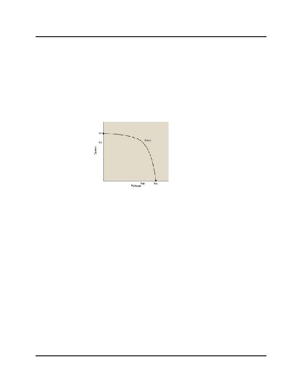
�example� photovoltaic� cell� operating� curve� is� shown� below.� Output� impedance,� operating� voltage,� and� peak�
�power� point� can� also� be� verified� by� empirical� measurements.� To� do� this,� measure� the� load� voltage� and� current�
�as� a� variable� load� impedance� across� the� transducer� is� swept� over� a� broad� enough� range� where� the� peak� power�
�point� can� be� found� by� finding� the� maximum� product� of� the� measured� load� voltage� and� current.�
�V� OC� :� Open-circuit� voltage�
�I� SC� :� Short-circuit� current�
�V� OP� :� Optimum� operating� voltage�
�I� OP� :� Optimum� operating� current�
�P� MAX� :� Maximum� operating� power�
�Current-Voltage� Curve�
�To� configure� the� CBC5300� to� work� with� a� given� transducer,� the� optimal� transducer� operating� voltage� point�
�must� first� be� obtained� though� the� manufacturer’s� data� sheet� or� from� empirical� measurements.� Next� calculate�
�the� values� needed� for� a� voltage� divider� to� set� the� operating� voltage� point� on� the� V� OPER� pin� (pin� 10).� The� top�
�of� the� voltage� divider� shown� in� Figure� 3� uses� V� REG� (pin� 11)� as� its� voltage� source;� the� bottom� of� the� voltage�
�divider� is� connected� to� ground.� V� OPER� is� equal� to� V� REG� *� (R2� /� (R1� +� R2)),� where� V� REG� is� nominally� 4.06V� and�
�R2� (bottom� resistor)� is� in� the� range� of� 500k?� to� 1M?� with� the� optimal� value� around� 750k?.� Note:� Better�
�circuit� performance� (i.e.,� less� input� ripple� voltage)� will� be� obtained� if� R2� is� made� smaller� than� 750k?.� A� more�
�useful� formula� is:� R1� =� R2� *� ((V� REG� /� V� OPER� )� -� 1).� Example:� For� a� 1k?� photovoltaic� cell� with� operating� voltage� of�
�1.01V,� R1� can� be� determined� as� R1� =� 1M?� *� ((4.06V� /� 1.01V)� -� 1)� =� 3.02M?.� A� 3.01M?� resistor� is� the� nearest�
�standard� value.� R2� was� chosen� as� a� standard� resistor� value.� 750k?� for� R2� is� also� a� standard� resistor� value� but�
�the� V� OPER� voltage� will� be� further� away� from� nominal� due� to� the� standard� resistor� values� available� for� R1.�
�Capacitor� C1� (47μF)� is� used� to� set� the� bandwidth� of� the� boost� converter� control� loop.� If� a� low� impedance�
�transducer� is� used� the� value� of� C1� might� have� to� be� reduced� in� value.� This� can� be� verified� using� an� oscilloscope�
�to� check� the� waveform� on� GATE� (pin� 3).� The� waveform� should� be� three� pulses� followed� by� a� longer� interval,�
�followed� again� by� three� pulses.� The� three� pulses� will� have� approximately� 16.7μs� of� high� duration� followed� by�
�16.7μs� of� low� duration.� If� more� than� three� pulses� are� in� the� waveform� then� the� value� of� C1� should� be� reduced�
�to� obtain� the� nominal� waveform.�
�Setting� the� Under� Voltage� Lockout� Voltage�
�The� under� voltage� lockout� (UVLO� SEL)� voltage� should� be� set� at� or� above� the� operating� point,� V� OPER,� in� order� to�
�prevent� the� EnerChip� from� inadvertently� powering� the� boost� converter� when� insufficient� input� transducer� power�
�is� available.� Normally,� UVLO� should� be� set� to� a� value� that� is� 20%� to� 80%� above� V� OPER.� UVLO� SEL� can� be� set� by�
�adding� one� or� more� series� diodes� between� UVLO� SEL� and� V� IN.� For� example,� the� nominal� voltage� at� UVLO� SEL� is�
�700mV;� to� raise� it� to� 1.4V,� insert� one� standard� silicon� diode.� To� reach� intermediate� voltages,� Schottky� diodes�
�may� be� used.�
�DS-72-06� Rev06�
�?2009� Cymbet� Corporation� ?� Tel:� +1-763-633-1780� ?� www.cymbet.com�
�Page� 7� of� 11�
�相关PDF资料 |
PDF描述 |
|---|---|
| CC-ACC-MX51-ETM | ADAPTER TRACE ETM/ETB JTAG |
| CDBMCU-DEBUG | EVAL BD FOR DSP CS48X & CS49X |
| CEL2MUSB | E2GO CELL PHONE CHARGER USB |
| CH-14403 | RACK SMALL MNT CHASSIS ALUMINUM |
| CH15MNP4 | BATT CHARGER 15MINUTE W/4AA |
相关代理商/技术参数 |
参数描述 |
|---|---|
| CBC-702 | 制造商:American Electronic Components Inc 功能描述:MERCURY RELAYS |
| CBC-707 | 制造商:American Electronic Components Inc 功能描述:MERCURY RELAYS |
| CBC-719 | 制造商:American Electronic Components / DURAKOOL 功能描述:MERCURY RELAY, 12VDC, 100A, SPDT; Coil Voltage VDC Nom:12V; Contact Current Max:100A; Coil Resistance:27ohm; Contact Configuration:SPDT; Relay Mounting:(Not Available) |
| CB-C8 | 制造商:NEC 制造商全称:NEC 功能描述:3-VOLT, 0.5-MICRON CELL-BASED CMOS ASIC |
| CBC-8 | 功能描述:断路器 CIRCUIT BREAKER RoHS:否 制造商:Phoenix Contact 产品:Device Circuit Breakers 产品类型:Thermomagnetic 电流额定值:2 A 电压额定值 AC:240 V, 277 V 电压额定值 DC:50 V 极数:1 Pole 执行器类型:Slide 电路功能:Trip Free 系列:CB TM1 工作温度范围:- 30 C to + 60 C 照明:No |
发布紧急采购,3分钟左右您将得到回复。