- 您现在的位置:买卖IC网 > PDF目录1908 > CC-2401K2A-CS (Copeland Communications Inc)MODEM 2400BAUD SECURE 3.3V PDF资料下载
参数资料
| 型号: | CC-2401K2A-CS |
| 厂商: | Copeland Communications Inc |
| 文件页数: | 7/66页 |
| 文件大小: | 0K |
| 描述: | MODEM 2400BAUD SECURE 3.3V |
| 标准包装: | 30 |
| 数据格式: | V.21,V.22,V.23,Bell 103 |
| 波特率: | 2.4k |
| 电源电压: | 3 V ~ 3.6 V |
| 安装类型: | 表面贴装 |
| 封装/外壳: | 模块 |
| 包装: | 散装 |
| 配用: | 539-1002-ND - KIT EVALUATION WORLD MODEM II |
| 其它名称: | 539-1010 CC-2401K2A-CS-ND |
第1页第2页第3页第4页第5页第6页当前第7页第8页第9页第10页第11页第12页第13页第14页第15页第16页第17页第18页第19页第20页第21页第22页第23页第24页第25页第26页第27页第28页第29页第30页第31页第32页第33页第34页第35页第36页第37页第38页第39页第40页第41页第42页第43页第44页第45页第46页第47页第48页第49页第50页第51页第52页第53页第54页第55页第56页第57页第58页第59页第60页第61页第62页第63页第64页第65页第66页
Data Sheet
CC-2401K2
Page 15 of 66
2007, Copeland Communications, Inc.
CC-2401K2 Datasheet Rev 1.5
2.
When the frame is complete, the host should simply stop sending data to the CC-2401. Since the CC-
2401 does not yet recognize the end of frame, it expects an extra byte and asserts CTS. If CTS is used to
cause a host interrupt, this final interrupt should be ignored by the host.
3.
When the CC-2401 is ready to send the next byte, if it has not yet received any data from the host, it
recognizes this as an end of frame, raises CTS, calculates the final CRC code, transmits the code and
begins transmitting stop flags.
4.
After transmitting the first stop flag, the CC-2401 lowers CTS indicating that it is ready to receive the next
frame from the host. At this point, the process begins again at step 1.
The method for receiving HDLC frames follows:
1.
After the call is connected, the CC-2401 searches for flag data. Once the first non flag word is detected,
the CRC is continuously computed and the data is sent across the UART to the host after removing the
HDLC zero-bit insertion. The DTE rate of the host must be at least as high as that of data transmission.
HDLC mode only works with 8 bit data words; the ninth bit is used only for escape on TXD and end of
frame received (EOFR) on RXD.
2.
When the CC-2401 detects the stop flag, it sends the last data word in the frame as well as the two CRC
bytes and determine if the CRC checksum matches. Thus, the last two bytes are not frame data but are
the CRC bytes, which can be discarded by the host. If the checksum matches, the CC-2401 sends “G”
(good). If the checksum does not match, the CC-2401 sends “e” (error). In addition, if the CC-2401
detects an abort (seven or more contiguous ones), it sends an “A”. When the “G”, “e”, or “A” (referred to
as a frame result word) is sent, the CC-2401 raises the EOFR (end of frame receive) pin. The GPIO1 pin
must be configured as EOFR by setting SE4[3](GPE) = 1. In addition to using the EOFR pin to indicate
that the byte is a frame result word, if in 9 bit data mode, (set S15[0] (NBE) = 1), the ninth bit is raised if
the byte is a frame result word. To program this mode, set S0C[3] (9BF) = 1 and SE0[3] (ND) = 1.
3.
When the next frame of data is detected, EOFR is lowered and the process repeats with step 1.
When receiving HDLC frames, the host begins receiving data asynchronously from the CC-2401. When each
byte is received, the host should check the EOFR pin (or the ninth data bit). If the EOFR pin (or ninth data bit)
is low, the data is valid frame data. If the EOFR pin (or ninth bit) is high, the data is a frame result word.
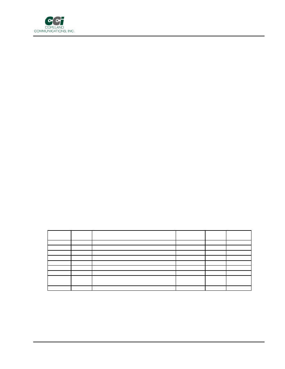
Fast Connect
In modem applications that require fast connection times, it is possible to reduce the length of the handshake.
Additional modem handshaking control can be adjusted through the registers shown in the following table.
These registers are most useful if the user has control of both the originating and answering modems. When
the fast connect settings are used, there may be unintended data received initially. The host must tolerate
these bytes.
Register
Name
Function
Units
Default
Fast
Connect
S1E
TATL
Transmit Answer Tone Length
1 s
0x03
00
S1F
ATTD
Answer Ton to Transmit Delay
5/3 ms
0x2D
00
S20
UNL
Unscrambled Ones Length-V.22
5/3 ms
0x5D
00
S21
TSOD
Transmit Scrambled Ones Delay – V.22
53.3 ms
0x09
00
S22
TSOL
Transmit Scrambled Ones Length – V.22
5/3 ms
0xA2
00
S23
VDDL
V.22/22b Data Delay Low
5/3 ms
0xCB
00
S24
VDDH
V.22/22b Data Delay High
(256) 5/3 ms
0x08
00
S34
TASL
Answer Tone Length
(only used in S1E[TATL] = 0x00)
5/3 ms
0x5A
F0
S35
RSOL
Receive V.22 Scrambled Ones Length
5/3 ms
0xA2
00
相关PDF资料 |
PDF描述 |
|---|---|
| CC-2434K2-CS5 | MODEM FAX 33K 5V |
| CC-24K2N-CS5 | MODEM WORLD NET 2400BAUD 5V |
| CC-92K2-IS | MODEM 56KBAUD V.90 SERIAL 3.3V |
| CC-MX-LB69-ZM | CONNECTCORE I.MX51 MODULE |
| CD22M3494MQZ96 | IC CROSSPOINT SWITCH 16X8 44PLCC |
相关代理商/技术参数 |
参数描述 |
|---|---|
| CC-2401K2A-CS5 | 功能描述:MODEM 2400BAUD SECURE 5V RoHS:否 类别:集成电路 (IC) >> 接口 - 调制解调器 - IC 和模块 系列:- 标准包装:25 系列:- 数据格式:V.21,V.22,V.23,V.29,V.32,V.34,V.90,V.92,Bell 103,Bell 212A 波特率:33.6k 电源电压:3.3V 安装类型:- 封装/外壳:- 供应商设备封装:- 包装:托盘 配用:591-1013-ND - KIT DEV SOCKETMODEM PARALLEL591-1009-ND - KIT DEV SRL SOCKETMODEM UNIVERSL 其它名称:MT5656SMI-P-V-34.R2-SPMT5656SMI-P-V-34.R2-SP-NDQ4711574 |
| CC24020N | 制造商:POWEREX 制造商全称:Powerex Power Semiconductors 功能描述:Super Fast Recovery Dual Diode Modules 20 Amperes/300-600 Volts |
| CC2403020N | 制造商:POWEREX 制造商全称:Powerex Power Semiconductors 功能描述:Super Fast Recovery Dual Diode Modules 20 Amperes/300-600 Volts |
| CC2403500N | 制造商:POWEREX 制造商全称:Powerex Power Semiconductors 功能描述:Super Fast Recovery Dual Diode Modules 50 Amperes/300-600 Volts |
| CC-2404K2A-CS | 功能描述:MODEM 2400BAUD SERIAL 3.3V RoHS:否 类别:集成电路 (IC) >> 接口 - 调制解调器 - IC 和模块 系列:- 标准包装:25 系列:- 数据格式:V.21,V.22,V.23,V.29,V.32,V.34,V.90,V.92,Bell 103,Bell 212A 波特率:33.6k 电源电压:3.3V 安装类型:- 封装/外壳:- 供应商设备封装:- 包装:托盘 配用:591-1013-ND - KIT DEV SOCKETMODEM PARALLEL591-1009-ND - KIT DEV SRL SOCKETMODEM UNIVERSL 其它名称:MT5656SMI-P-V-34.R2-SPMT5656SMI-P-V-34.R2-SP-NDQ4711574 |
发布紧急采购,3分钟左右您将得到回复。