- 您现在的位置:买卖IC网 > Datasheet目录968 > CC2520FC-1.5-1% (Caddock Electronics Inc)RES 1.50 OHM 1.5W 1% 2512 Datasheet资料下载
参数资料
| 型号: | CC2520FC-1.5-1% |
| 厂商: | Caddock Electronics Inc |
| 文件页数: | 2/2页 |
| 文件大小: | 0K |
| 描述: | RES 1.50 OHM 1.5W 1% 2512 |
| 标准包装: | 50 |
| 系列: | CC |
| 电阻(欧姆): | 1.5 |
| 功率(瓦特): | 1.5W |
| 复合体: | 陶瓷 |
| 特点: | 电流感应,脉冲耐受 |
| 温度系数: | -20/ +80ppm/°C |
| 容差: | ±1% |
| 封装/外壳: | 2520(6450 公制) |
| 尺寸/尺寸: | 0.250" L x 0.200" W(6.35mm x 5.08mm) |
| 高度: | 0.045"(1.14mm) |
| 端子数: | 2 |
| 包装: | 散装 |
| 其它名称: | Q7040694 |
�� �
�
�Type� CC� Low� Resistance� Precision� Chip� Resistors�
�Page� 2� of� 2�
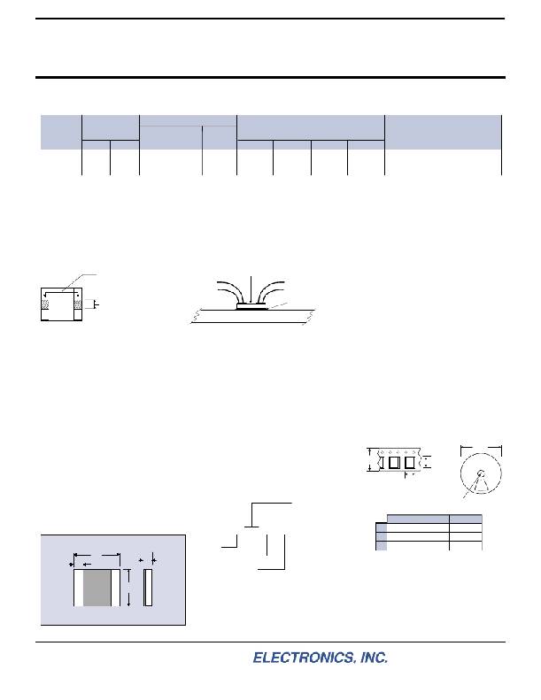
�Style� WB� -� Wire� Bond� Version�
�is� a� hybrid� mountable� version� with� metallized� pads� for� wire� bonding� utilizing� aluminum� wire� and�
�a� metallized� back� surface� for� solder� attachment� of� the� back� surface� to� a� heat� sinking� substrate.�
�R� θ� JC� Max.� Chip�
�Model�
�Resistance�
�Min.� Max.�
�Power� Capability� Information�
�Thermal� Resistance�
�Film� (J)� to� Solder� Pad� (C)� Temperature�
�(see� note� 3)�
�A�
�Dimensions� in� inches� and� (millimeters)�
�B� C�
�D�
�Comments�
�CC2015WB�
�CC2520WB�
�0.020� ?�
�0.025� ?�
�10.0� ?�
�10.0� ?�
�13.9� °� C/Watt�
�8.33� °� C/Watt�
�150� °� C�
�150� °� C�
�.200� ±� .007�
�(5.08� ±� .18)�
�.250� ±� .007�
�(6.35� ±� .18)�
�.150� ±� .007�
�(3.81� ±� .18)�
�.200� ±� .007�
�(5.08� ±� .18)�
�.027� ±� .003�
�(.69� ±� .08)�
�.027� ±� .003�
�(.69� ±� .08)�
�.050� min.�
�(1.27� min.)�
�.040� min.�
�(1.02� min.)�
�Aluminum� wire� to� be� used� for� bonding�
�Aluminum� wire� to� be� used� for� bonding�
�made� in� the� crosshatched�
�.055� (1.40)� centered� Solder� pad,� soldered�
�Note� 3:� Thermal� Resistance� -� In� High� Power� Applications� where� the� circuit� board� material�
�provides� high� heat� sinking� bene?ts� (such� as� IMS,� Alumina,� or� other)� the� thermal� resistance� of�
�the� chip� resistor� is� useful� to� establish� the� maximum� power� capability� of� the� chip� resistor� in� the�
�application.� The� ?lm� temperature� is� measured� at� the� center� of� the� resistor� element� and� the�
�solder� pad� temperature� is� measured� at� the� soldered� interface� with� the� circuit� board.� Maximum�
�temperature� of� the� chip� resistor� (at� the� center� of� chip)� should� not� exceed� 150°C� through� the�
�temperature� range� of� the� application.�
�Location� for� Sense� (Potential)� Connection:�
�Sense� connection� shall� be� Film� Temperature�
�Measuring� Point�
�portion� of� the� termination� Sense� Wire� Sense� Wire�
�pad.� Current� Wire� Current� Wire�
�interface� with� circuit� board.�
�Circuit� board:� IMS,� Ceramic� (Alumina)� ,� or� other.�
�WB� Resistor� mounting�
�CC2015WB� Standard� Resistance� Values:�
�Tolerance� CC2015WB� ±1%� Standard� (except� as� noted).�
�0.020� Ω� 5%� 0.050� Ω� 2%� 0.25� Ω� 0.75� Ω� 3.30� Ω�
�0.025� Ω� 5%� 0.075� Ω� 2%� 0.30� Ω� 1.00� Ω� 4.00� Ω�
�0.030� Ω� 5%� 0.10� Ω� 0.33� Ω� 1.50� Ω� 5.00� Ω�
�0.033� Ω� 5%� 0.15� Ω� 0.40� Ω� 2.00� Ω� 7.50� Ω�
�0.040� Ω� 5%� 0.20� Ω� 0.50� Ω� 2.50� Ω� 8.00� Ω�
�3.00� Ω� 10.0� Ω�
�CC2520WB� Standard� Resistance� Values:�
�Tolerance� CC2520WB� ±1%� Standard� (except� as� noted).�
�0.025� Ω� 5%� 0.050� Ω� 2%� 0.25� Ω� 0.75� Ω� 3.30� Ω�
�0.030� Ω� 5%� 0.075� Ω� 2%� 0.30� Ω� 1.00� Ω� 4.00� Ω�
�0.033� Ω� 5%� 0.10� Ω� 0.33� Ω� 1.50� Ω� 5.00� Ω�
�0.040� Ω� 5%� 0.15� Ω� 0.40� Ω� 2.00� Ω� 7.50� Ω�
�0.20� Ω� 0.50� Ω� 2.50� Ω� 8.00� Ω�
�3.00� Ω� 10.0� Ω�
�Custom� resistance� values� and� non-standard� tolerances�
�can� be� manufactured� for� high� quantity� applications.�
�Please� contact� Caddock� Applications� Engineering.�
�General� Information� for� Type� CC� -� Style� FC� and� Style� WB� -� Chip� Resistors�
�Speci?cations:�
�C�
�Information:� 1512� =� 0.150”� x� 0.120”�
�Style:�
�FC� or� WB�
�Temperature� Coef?cient:� TC� referenced� to�
�+25°C,� Δ� R� taken� at� +150°C.�
�0.50� ohm� and� above,� -20� to� +80� ppm/°C�
�0.050� ohm� to� 0.49� ohm,� 0� to� +200� ppm/°C�
�below� 0.050� ohm,� 0� to� +300� ppm/°C.�
�Inductance:� Less� than� 5� nH� typical.�
�Load� Life:� 1000� hours� at� rated� power,� based�
�upon� 150°C� max.� chip� temperature,�
�Δ� R� ±� (0.5%� +� 0.0005� ohm).�
�Momentary� Overload:� 1.5� times� rated� power,�
�for� 5� seconds,� Δ� R� ±� (0.5%� +� 0.0005� ohm).�
�Operating� Temperature:� -55°C� to� +150°C.�
�Measurement� Note:� All� measurements� are�
�taken� using� Kelvin� connections� per� the�
�recommended� connection� locations.�
�A�
�D�
�B�
�Dimensions� in� inches� and� (millimeters)�
�Solder� attachment� note:�
�Style� FC� has� a� bare� ceramic� back� surface.�
�The� recommended� solders� for� ?ip� chip�
�solder� attachment� are� 62Sn� /� 36Pb� /� 2Ag,�
�96.5Sn� /� 3.5Ag,� or� standard� Sn� /� Ag� /� Cu�
�solder� alloys.�
�Style� WB� has� a� metallized� back� surface� for�
�soldering� to� a� substrate� or� a� heat� sink.� The�
�recommended� solders� to� be� used� are�
�62Sn� /� 36Pb� /� 2Ag,� 96.5Sn� /� 3.5Ag,� or�
�standard� Sn� /� Ag� /� Cu� solder� alloys.�
�Ordering� Physical� Size�
�2015� =� 0.200”� x� 0.150”�
�2520� =� 0.250”� x� 0.200”�
�CC� 2520� FC� -� 0.10� -� 1%�
�Tolerance:�
�Type� CC� ±� 5%� below� 0.050� ?�
�±� 2%� 0.050� ?� to� 0.099� ?�
�±� 1%� 0.10� ?� and� above�
�Resistor� Value� (� ?� )�
�See� charts� for� availability�
�Packaging� information:�
�Style� FC� ,� ?ip� chip� resistors,� are� shipped� with� the� bare�
�ceramic� side� up� in� the� pocket,� with� the� solderable� pads� fac-�
�ing� down.�
�Style� WB� ,� wire� bondable� resistors,� are� shipped� with� the�
�wire� bondable� pads� facing� up� in� the� pocket.�
�The� illustration� shows� the� orientation� of� the� CC1512� and�
�CC2015� chip� resistors� in� the� tape.� The� CC2520� chip� resistors�
�are� rotated� 90°� from� what� is� shown� in� the� illustration.�
�7”� dia.�
�(178� mm)�
�12mm�
�0.473”� Bo�
�Ao�
�Ko� signifies� tape� thickness� and� dimension�
�.512”� arbor� hole�
�(13mm)�
�Size� 1512� Size� 2015� Size� 2520�
�Ao� 0.135”� (3.43mm)� 0.189”� (4.80mm)� 0.271”� (6.88mm)�
�Bo� 0.167”� (4.24mm)� 0.209”� (5.31mm)� 0.216”� (5.49mm)�
�Ko� 0.037”� (0.94mm)� 0.087”� (2.21mm)� 0.066”� (1.68mm)�
�Carrier� Tape� and� pocket� dimensions:�
�Tape� is� 12mm� Carrier� Tape� (8mm� pitch)�
�Full� reel� quantities:�
�1500� pieces� per� reel� for� CC1512�
�1000� pieces� per� reel� for� CC2015� and� CC2520�
�Quantities� of� less� than� 250� will� be� shipped� in� tape� without� reel� and�
�without� tape� leader� at� the� option� of� Caddock.�
�Tape� dimensions� and� materials� will� be� consistent� with� EIA-481-1.�
�Reels� will� be� marked� with� a� label� containing� Caddock� logo,� part�
�number,� resistor� value,� tolerance,� packaging� date,� and� quantity.�
�Applications� Engineering�
�17271� North� Umpqua� Hwy.�
�Roseburg,� Oregon� 97470-9422�
�Phone:� (541)� 496-0700�
�Fax:� (541)� 496-0408�
�?� 2004� Caddock� Electronics,� Inc.�
�e-mail:� DOCK�
�CAD� caddock@caddock.com� ?� web:� www.caddock.com�
�For� Caddock� Distributors� listed� by� country� see� caddock.com/contact/dist.html�
�Sales� and� Corporate� Of?ce�
�1717� Chicago� Avenue�
�Riverside,� California� 92507-2364�
�Phone:� (951)� 788-1700�
�Fax:� (951)� 369-1151�
�28_IL106.1004�
�相关PDF资料 |
PDF描述 |
|---|---|
| CC2691-000 | MOLDED BOOT |
| CC4850W4VRH | RELAY SSR DUAL 50A RNDM PNL MNT |
| CCASMA-MM-LL142-60 | RF CABLE SMA ARMOR LOWLOSS 18GHZ |
| CCBNS-MM-RG316DS-12 | RF CABLE SMA/BNC M/M RG316DS 12" |
| CCESMA-MM-SS402-120 | RF COAX CABLE EZEE 18 GHZ 120" |
相关代理商/技术参数 |
参数描述 |
|---|---|
| CC2520RHDR | 功能描述:射频收发器 2nd Gen 2.4 GHz Zig Bee transceiver RoHS:否 制造商:Atmel 频率范围:2322 MHz to 2527 MHz 最大数据速率:2000 Kbps 调制格式:OQPSK 输出功率:4 dBm 类型: 工作电源电压:1.8 V to 3.6 V 最大工作温度:+ 85 C 接口类型:SPI 封装 / 箱体:QFN-32 封装:Tray |
| CC2520RHDRG4 | 功能描述:射频收发器 2.4GHz ZigBee/IEEE 802.15.4RF Xceiver RoHS:否 制造商:Atmel 频率范围:2322 MHz to 2527 MHz 最大数据速率:2000 Kbps 调制格式:OQPSK 输出功率:4 dBm 类型: 工作电源电压:1.8 V to 3.6 V 最大工作温度:+ 85 C 接口类型:SPI 封装 / 箱体:QFN-32 封装:Tray |
| CC2520RHDT | 功能描述:射频收发器 2nd Gen 2.4 GHz Zig Bee transceiver RoHS:否 制造商:Atmel 频率范围:2322 MHz to 2527 MHz 最大数据速率:2000 Kbps 调制格式:OQPSK 输出功率:4 dBm 类型: 工作电源电压:1.8 V to 3.6 V 最大工作温度:+ 85 C 接口类型:SPI 封装 / 箱体:QFN-32 封装:Tray |
| CC2520RHDTG4 | 功能描述:射频收发器 2nd Gen 2.4 GHz Zig Bee/IEEE RF Xcvr RoHS:否 制造商:Atmel 频率范围:2322 MHz to 2527 MHz 最大数据速率:2000 Kbps 调制格式:OQPSK 输出功率:4 dBm 类型: 工作电源电压:1.8 V to 3.6 V 最大工作温度:+ 85 C 接口类型:SPI 封装 / 箱体:QFN-32 封装:Tray |
发布紧急采购,3分钟左右您将得到回复。