- 您现在的位置:买卖IC网 > PDF目录298946 > CD-700-KAC-GGB-24.960 (VECTRON INTERNATIONAL) PHASE LOCKED LOOP, CQCC16 PDF资料下载
参数资料
| 型号: | CD-700-KAC-GGB-24.960 |
| 厂商: | VECTRON INTERNATIONAL |
| 元件分类: | XO, clock |
| 英文描述: | PHASE LOCKED LOOP, CQCC16 |
| 封装: | HERMETIC SEALED, CERAMIC, SMD-16 |
| 文件页数: | 1/2页 |
| 文件大小: | 115K |
| 代理商: | CD-700-KAC-GGB-24.960 |
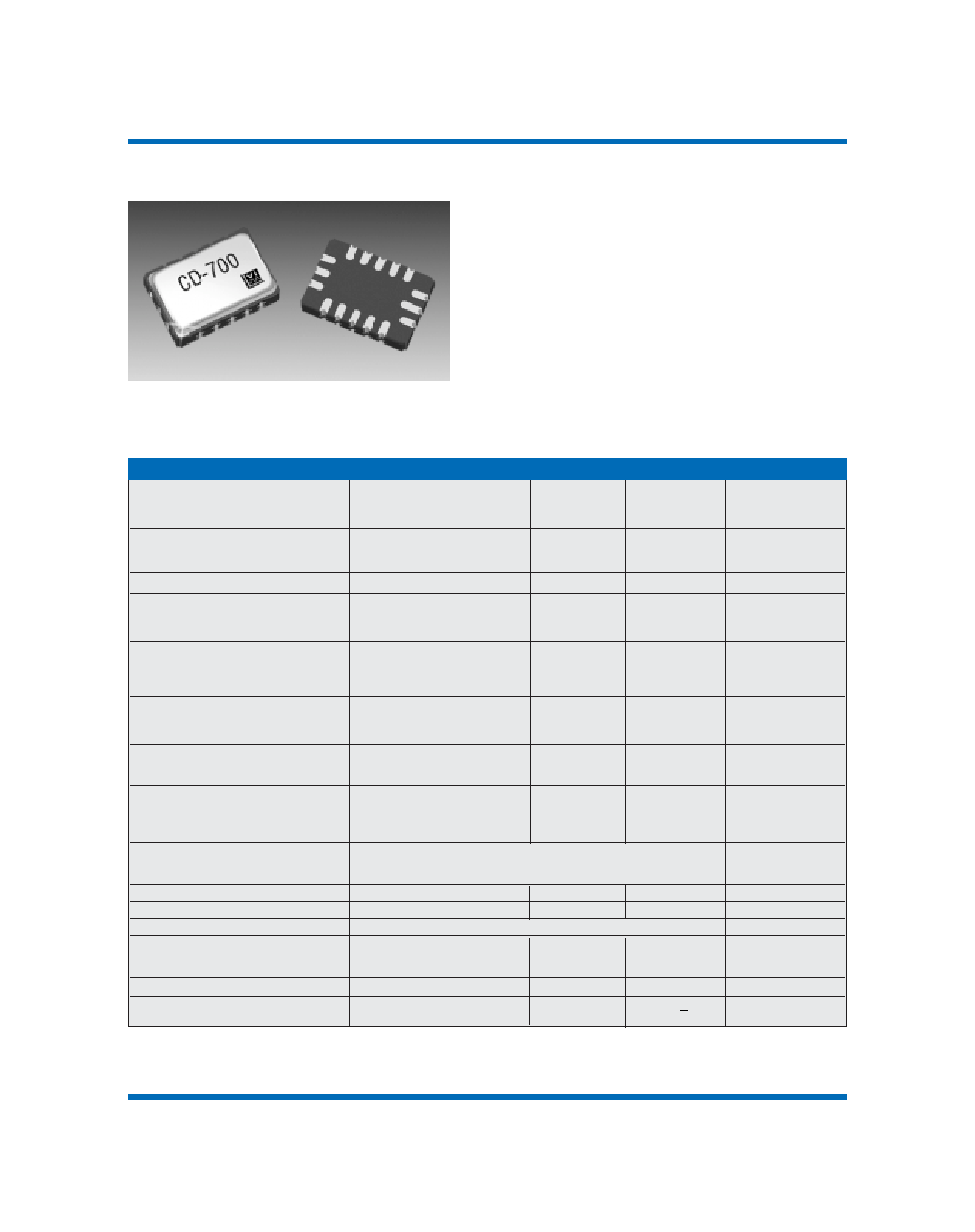
CD-700
Clock and Data Recovery Products
Performance Characteristics
Output Frequency: (ordering option)
Out 1, 5V option
12.000
65.536
MHz
Out 1, 3.3V option
12.000
51.840
MHz
Supply Voltage1:VDD
+5.0
4.5
5.0
5.5
V
+3.3
3.0
3.3
V
Supply Current:
I
DD
63
mA
Output Logic Levels:
Output Logic High
V
OH
2.5
V
Output Logic Low
VOL
0.5
V
Output Transition Times:
Rise Time2
tR
5ns
Fall Time2
tF
5ns
Input Logic Levels:
Input Logic High2
VIH
2.0
V
Input Logic Low2
VOL
0.5
V
Nominal Frequency on Loss of Signal
Output 1
±75
ppm
Output 2
±75
ppm
Symmetry or Duty Cycle2
Out 1
SYM1
40
60
%
Out 2
SYM2
45
55
%
RCLK
40
60
%
Absolute Pull Range
APR
±50, ±80, ±100
ppm
(ordering option)
over operating temp, aging, p.s. variations
Test Conditions for APR (+5V option)
VC
0.5
4.5
V
Test Conditions for APR (+3.3V option)
VC
0.3
3.0
V
Transfer Function
Positive
Phase Detector Gain
+5.0V option
0.53
rad/V
+3.3V option
0.35
rad/V
Operating temperature (ordering option)
0/70 or -40/85
oC
Control Voltage Leakage Current
IVCXO
+1uA
1. A 0.01 uF capacitor should be located as close to the supply as possible (to ground) and a 0.1 uF is also recommended.
2. Symmetry is defined as (ON TIME/PERIOD) with VS = 1.4V for both 5V and 3.3V operation.
Description:
Vectron’s CD-700 is a user-configurable crystal based
PLL integrated circuit. It includes a digital phase
detector, op-amp, VCXO and additional integrated
functions for use in digital synchronization
applications
Features:
5 x 7.5mm, smallest VCXO PLL available
Output Frequencies to 65.536 MHz
5 or 3.3 Vdc operation
Tri-state Output
Loss of Signal Alarm
VCXO with CMOS outputs
0/70 or -40/85°C temperature range
Hermetically sealed ceramic SMD package
Parameter
Symbol
Min.
Typical
Max
Unit
Vectron International 267 Lowell Road, Hudson, NH 03051 Tel: 1-88-VECTRON-1 Web: www.vectron.com
100
8798_AA's Vectron
05/30/02
3:12 PM
Page 100
相关PDF资料 |
PDF描述 |
|---|---|
| CD-700-LAC-NEB-62.208 | PHASE LOCKED LOOP, CQCC16 |
| CD-700-LAF-GKB-62.208 | PHASE LOCKED LOOP, CQCC16 |
| CD-700-LAF-NGB-62.500 | PHASE LOCKED LOOP, CQCC16 |
| CD-700-LAC-NCB-24.960 | PHASE LOCKED LOOP, CQCC16 |
| CD-700-LAF-GFB-60.000 | PHASE LOCKED LOOP, CQCC16 |
相关代理商/技术参数 |
参数描述 |
|---|---|
| CD-700-KAC-GGB-25.000 | 制造商:未知厂家 制造商全称:未知厂家 功能描述:Phase-Locked Loop |
| CD-700-KAC-GGB-27.000 | 制造商:未知厂家 制造商全称:未知厂家 功能描述:Phase-Locked Loop |
| CD-700-KAC-GGB-28.704 | 制造商:未知厂家 制造商全称:未知厂家 功能描述:Phase-Locked Loop |
| CD-700-KAC-GGB-30.000 | 制造商:未知厂家 制造商全称:未知厂家 功能描述:Phase-Locked Loop |
| CD-700-KAC-GGB-30.720 | 制造商:未知厂家 制造商全称:未知厂家 功能描述:Phase-Locked Loop |
发布紧急采购,3分钟左右您将得到回复。