- 您现在的位置:买卖IC网 > PDF目录16821 > CDB8427 (Cirrus Logic Inc)EVALUATION BOARD FOR CS8427 PDF资料下载
参数资料
| 型号: | CDB8427 |
| 厂商: | Cirrus Logic Inc |
| 文件页数: | 6/10页 |
| 文件大小: | 0K |
| 描述: | EVALUATION BOARD FOR CS8427 |
| 标准包装: | 1 |
| 主要目的: | 音频,采样率转换器 |
| 嵌入式: | 是,MCU,8 位 |
| 已用 IC / 零件: | CS8427 |
| 主要属性: | 带数字音频发射器和接收器的采样率转换器 |
| 次要属性: | 48 kHz 输出采样率,AES/EBU,S/PDIF,EIAJ-340,GUI |
| 已供物品: | 板 |
| 产品目录页面: | 759 (CN2011-ZH PDF) |
| 相关产品: | 598-1735-ND - IC TXRX DGTL AUDIO 96KHZ 28TSSOP 598-1733-ND - IC TXRX DGTL AUDIO 96KHZ 28SOIC |
| 其它名称: | 598-1783 |
Micrel, Inc.
SM802111
April 2011
3
M9999-041111-A
hbwhelp@micrel.com
Absolute Maximum Ratings
(1)
Supply Voltage (VDD, VDDO) .........................................+4.6V
Input Voltage (VIN).............................. 0.50V to VDD + 0.5V
Lead Temperature (soldering, 20s)............................ 260°C
Case Temperature ..................................................... 115
°C
Storage Temperature (Ts) ......................... 65°C to +150°C
Operating Ratings
(2)
Supply Voltage (VDD, VDDO) .................. +2.375V to +3.465V
Ambient Temperature (TA) .......................... –40°C to +85°C
Junction Thermal Resistance
(3)
QFN (
θJA)
Still-Air.........................................................50
°C/W
QFN (
ψJB)
Junction-to-Board........................................30°C/W
DC Electrical Characteristics
(4)
VDD = VDDO = 3.3V ±5% or 2.5V ±5%
VDD = 3.3V ±5%, VDDO = 3.3V ±5% or 2.5V ±5%
TA = –40°C to +85°C
or (408) 955-1690
LVPECL DC Electrical Characteristics
(4)
VDD = VDDO 3.3V ±5% or 2.5V ±5%
VDD = 3.3V ±5%, VDDO = 3.3V ±5% or 2.5V ±5%
TA = –40°C to +85°C; RL = 50 to VDDO 2V
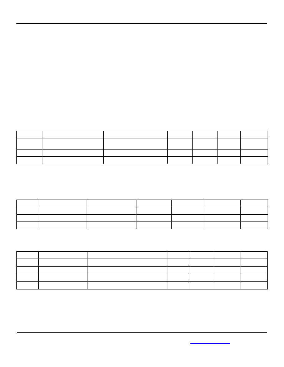
LVCMOS (PLL_BYPASS) DC Electrical Characteristics
(4)
VDD = 3.3V ±5% or 2.5V ±5%, TA = –40°C to +85°C
Symbol
Parameter
Condition
Min.
Typ.
Max.
Units
VIH
Input High Voltage
2
VDD + 0.3
V
VIL
Input Low Voltage
0.3
0.8
V
IIH
Input High Current
VDD = VIN = 3.465V
150
μA
IIL
Input Low Current
VDD = 3.465V, VIN = 0V
5
μA
Notes
:
1.
Permanent device damage may occur if absolute maximum ratings are exceeded. This is a stress rating only and functional operation is not
implied at conditions other than those detailed in the operational sections of this data sheet. Exposure to absolute maximum rating conditions for
extended periods may affect device reliability.
2.
The data sheet limits are not guaranteed if the device is operated beyond the operating ratings.
3.
Package thermal resistance assumes exposed pad is soldered (or equivalent) to the devices most negative potential on the PCB.
4.
The circuit is designed to meet the AC and DC specifications shown in the above table after thermal equilibrium has been established.
Symbol
Parameter
Condition
Min.
Typ.
Max.
Units
VDD, VDDO
2.5V Operating Voltage
2.375
2.5
2.625
V
VDD, VDDO
3.3V Operating Voltage
3.135
3.3
3.465
V
IDD
Supply Current, VDD + VDDO
Outputs open
91
115
mA
Symbol
Parameter
Condition
Min.
Typ.
Max.
Units
VOH
Output High Voltage
VDDO – 1.145
VDDO – 0.97
VDDO – 0.845
V
VOL
Output Low Voltage
VDDO – 1.945
VDDO – 1.77
VDDO – 1.645
V
VSWING
Output Voltage Swing
0.6
0.8
1.0
V
相关PDF资料 |
PDF描述 |
|---|---|
| RSH0E391MCN1GB | CAP ALUM 390UF 2.5V 20% SMD |
| EBA22DRMD-S288 | CONN EDGECARD 44POS .125 EXTEND |
| RS3-4809DZ/H2 | CONV DC/DC 3W 20-60VIN +/-09VOUT |
| 200LLE3R3MEFC6.3X11 | CAP ALUM 3.3UF 200V 20% RADIAL |
| NLCV32T-4R7M-PF | INDUCTOR POWER 4.7UH 1210 |
相关代理商/技术参数 |
参数描述 |
|---|---|
| CDB8952 | 制造商:Cirrus Logic 功能描述:NOT RECOMMENDED FOR NEW DESIGNS - USE CDB8952T - Bulk 制造商:Cirrus Logic 功能描述:Tools Development kit Kit Con |
| CDB8952T | 功能描述:以太网开发工具 Eval Bd 100BASE-TX/ 10BASE-T Transceiver RoHS:否 制造商:Micrel 产品:Evaluation Boards 类型:Ethernet Transceivers 工具用于评估:KSZ8873RLL 接口类型:RMII 工作电源电压: |
| CDB-9PF | 制造商:HRS 制造商全称:HRS 功能描述:CD CRIMP TYPE CONNECTOR |
| CDB-9SF | 制造商:HRS 制造商全称:HRS 功能描述:CD CRIMP TYPE CONNECTOR |
| CDBA1100 | 制造商:COMCHIP 制造商全称:Comchip Technology 功能描述:SMD Schottky Barrier Rectifier |
发布紧急采购,3分钟左右您将得到回复。