- 您现在的位置:买卖IC网 > PDF目录366865 > CKB-38-70120 Mid-Priced CMOS IC Time Delay Relay PDF资料下载
参数资料
| 型号: | CKB-38-70120 |
| 英文描述: | Mid-Priced CMOS IC Time Delay Relay |
| 中文描述: | 中档CMOS集成电路时间延迟继电器 |
| 文件页数: | 2/2页 |
| 文件大小: | 56K |
| 代理商: | CKB-38-70120 |
1225
Dimensions are shown for
reference purposes only.
Dimensions are in inches over
(mllimeters) unless otherwise
specified.
Specifications and availability
subject to change.
www.tycoelectronics.com
Technical support:
Refer to inside back cover.
P&B
Catalog 1308242
Issued 3-03
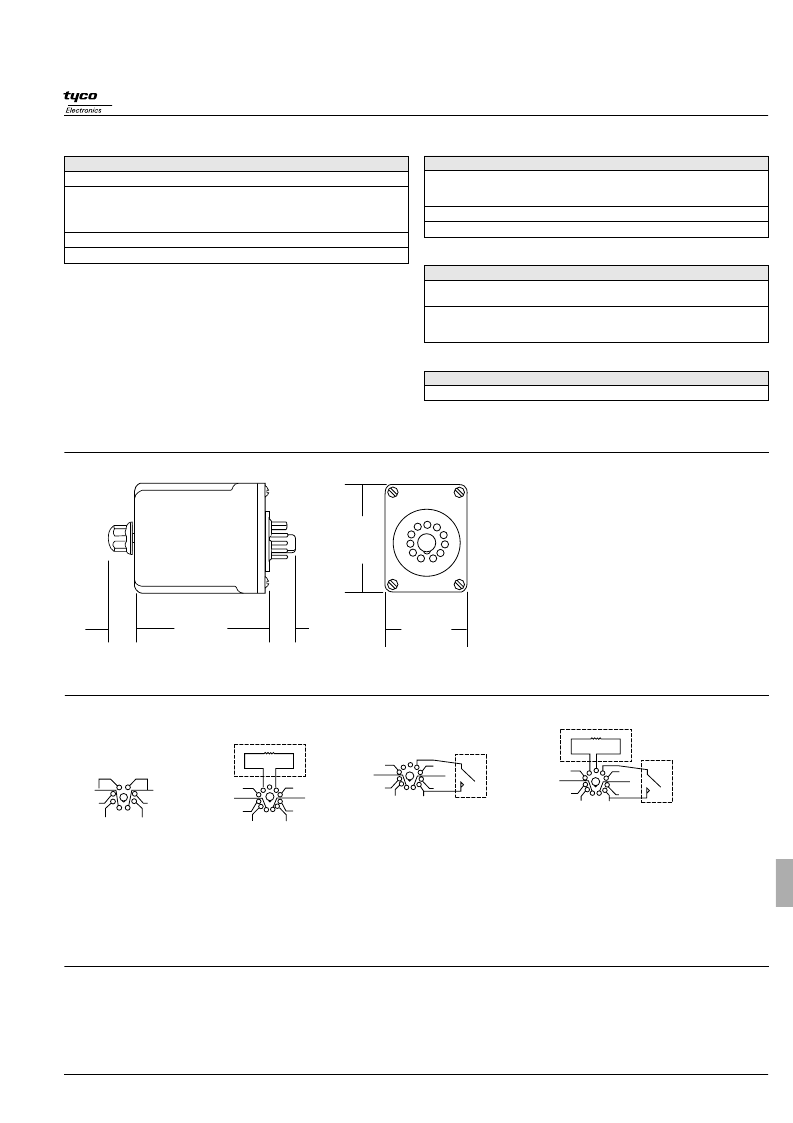
Wiring Diagrams – Bottom Views (pins numbered clockwise from keyway)
* If control switch is closed when power is applied, relay will immediately energize. A 50 millisecond minimum switch closure is required. IMPORTANT: A dry circuit switch is recommended. A
“
dry
circuit
”
switch is one rated to reliably switch currents of less than 50mA. Use of a switch rated for other than dry circuit may result in failure of the time delay relay to function properly.
**
Note:
Input polarity for DC operation. For most reliable operation on AC, connect high side to
“
+
”
and low side to
“–”
.
Ordering Information – Authorized distributors are more likely to stock boldface items listed below.
Outline Dimensions
External Resistor Chart
See External Resistor Selection Charts at beginning of Time Delay Relay section of this Databook.
Delay On Operate Models
Voltage
Time
24VAC
0.1 to 10 Sec.
0.1 to 10 Sec.
120VAC
0.6 to 60 Sec.
1.2 to 120 Sec.
1.8 to 180 Sec.
120VAC
0.1 to 10 Sec.
12VDC
0.1 to 10 Sec.
Adjustment
Knob
Wiring Dia.
1
Part Number
CKB-38-30010
CKB-38-70010
CKB-38-70060
CKB-38-70120
CKB-38-70180
CKF-38-70010
CKD-38-20010
Knob
1
Resistor
Knob
2
1
Delay On Release Models
Voltage
Time
0.1 to 10 Sec.
120VAC
0.6 to 60 Sec.
1.8 to 180 Sec.
120VAC
0.1 to 10 Sec.
24VDC
0.1 to 10 Sec.
Adjustment
Wiring Dia.
Part Number
CKB-38-78010
CKB-38-78060
CKB-38-78180
CKF-38-78010
CKH-38-38010
Knob
3
Resistor
Resistor
4
4
Delay On Dropout Models
Voltage
Time
24VAC
0.1 to 10 Sec.
0.6 to 60 Sec.
0.1 to 10 Sec.
120VAC
0.6 to 60 Sec.
1.2 to 120 Sec.
Adjustment
Knob
Wiring Dia.
1
Part Number
CKB-38-37010
CKB-38-37060
CKB-38-77010
CKB-38-77060
CKB-38-77120
Knob
1
Interval On Models
Voltage
120VAC
Time
0.1 to 10 Sec.
Adjustment
Knob
Wiring Dia.
3
Part Number
CKB-38-79010
.60
(15.2)
.56
(14.2)
2.937 MAX.
(74.6)
2.406 MAX.
(61.1)
1.781 MAX.
(45.2)
+
_
INPUT
(DC POLARITY INDICATED)**
Fig.1
8 Pin
EXTERNAL RESISTOR
INPUT
(DC POLARITY INDICATED)**
Fig. 2
11 Pin
+
_
CONTINUOUS
SUPPLY
INPUT
(DC POLARITY INDICATED)**
Fig. 3
11 Pin
EXTERNAL
CONTROL
SWITCH*
+
_
CONTINUOUS
SUPPLY
INPUT
(DC POLARITY INDICATED)**
Fig. 4
11 Pin
EXTERNAL
CONTROL
SWITCH*
EXTERNAL RESISTOR
+
_
相关PDF资料 |
PDF描述 |
|---|---|
| CKB-38-70180 | Mid-Priced CMOS IC Time Delay Relay |
| CKB-38-77010 | Mid-Priced CMOS IC Time Delay Relay |
| CKB-38-77060 | Mid-Priced CMOS IC Time Delay Relay |
| CKB-38-77120 | Mid-Priced CMOS IC Time Delay Relay |
| CKB-38-78010 | Mid-Priced CMOS IC Time Delay Relay |
相关代理商/技术参数 |
参数描述 |
|---|---|
| CKB-38-70180 | 功能描述:时间延迟和计时继电器 RELAY TIME DELAY DPDT 120 VAC 8 RoHS:否 制造商:Crydom 显示器类型:Hand Dial 电源电压:280 VAC 定时范围: 触点形式: 触点额定值:6 A 端接类型:DIN Rail |
| CKB-38-71067 | 功能描述:时间延迟和计时继电器 CKB-38-71067=RELAY,TD,OCTAL,DU RoHS:否 制造商:Crydom 显示器类型:Hand Dial 电源电压:280 VAC 定时范围: 触点形式: 触点额定值:6 A 端接类型:DIN Rail |
| CKB-38-71070 | 制造商:TE Connectivity 功能描述: |
| CKB-38-77010 | 功能描述:时间延迟和计时继电器 DPDT 10A 120VAC 0.1- 10sec.TIME DELAY RLY RoHS:否 制造商:Crydom 显示器类型:Hand Dial 电源电压:280 VAC 定时范围: 触点形式: 触点额定值:6 A 端接类型:DIN Rail |
| CKB-38-77060 | 功能描述:时间延迟和计时继电器 DPDT 10A 120VAC 0.6- 60sec.TIME DELAY RLY RoHS:否 制造商:Crydom 显示器类型:Hand Dial 电源电压:280 VAC 定时范围: 触点形式: 触点额定值:6 A 端接类型:DIN Rail |
发布紧急采购,3分钟左右您将得到回复。