参数资料
| 型号: | CL-90A |
| 厂商: | GE Sensing |
| 文件页数: | 3/4页 |
| 文件大小: | 0K |
| 描述: | NTC THERM CURR LIMIT INRUSH |
| 特色产品: | CL Series Current Limiters |
| 标准包装: | 2,000 |
| 系列: | CL |
| R @ 25°C: | 120 欧姆 |
| R @电流: | 1.18 欧姆 |
| 电流 - 稳态最大值: | 2A |
| 容差: | ±25% |
| 直径: | 0.93"(23.62mm) |
| 引线间隔: | 0.328"(8.33mm) |
| 包装: | 散装 |
| 其它名称: | AB15190 CL-90-A CL-90-A-ND Q2025121 Q2320551 |
�� �
�
�GE�
�Sensing�
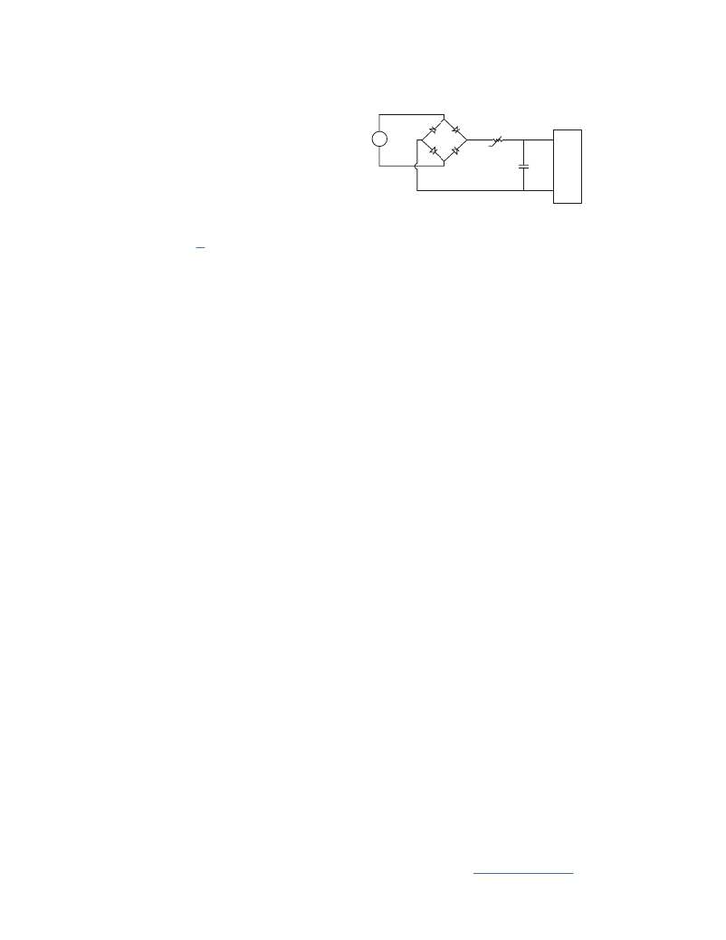
�Inrush� CurrentLimiters� In� Switching� Power� Supplies�
�The� problem� of� current� surges� in� switch-mode� power�
�supplies� is� caused� by� the� large� filter� capacitors� used� to�
�smooth� the� ripple� in� the� rectified� 60� Hz� current� prior� to�
�being� chopped� at� a� high� frequency.� The� diagram� above�
�~�
�R� I�
�-t� o�
�illustrates� a� circuit� commonly� used� in� switching� power�
�supplies.�
�In� the� circuit� above� the� maximum� current� at� turn-on� is�
�the� peak� line� voltage� divided� by� the� value� of� R;� for� 120� V,�
�it� is� approximately� 120� x� √� 2/R� I� .� Ideally,� during� turn-on� R� I�
�should� be� very� large,� and� after� the� supply� is� operating,�
�should� be� reduced� to� zero.� The� NTC� thermistor� is� ideally�
�suited� for� this� application.� It� limits� surge� current� by�
�functioning� as� a� power� resistor� which� drops� from� a� high�
�cold� resistance� to� a� low� hot� resistance� when� heated� by�
�the� current� flowing� through� it.� Some� of� the� factors� to�
�consider� when� designing� NTC� thermistor� as� an� inrush�
�or� in� differential� form:�
�Pdt� =� HdT� +� δ� (T� –� T� A� )dt�
�where:�
�P� =� Power� generated� in� the� NTC�
�t� =� Time�
�H� =� Heat� capacity� of� the� thermistor�
�T� =� Temperature� of� the� thermistor� body�
�δ� =� Dissipation� constant�
�T� A� =� Ambient� temperature�
�Typical� power�
�supply� circuit�
�current� limiter� are:�
�During� the� short� time� that� the� capacitors� are� charging�
�?�
�?�
�?�
�?�
�?�
�Maximum� permissible� surge� current� at� turn-on�
�Matching� the� thermistor� to� the� size� of� the� filter� capacitors�
�Maximum� value� of� steady� state� current�
�Maximum� ambient� temperature�
�Expected� life� of� the� power� supply�
�(usually� less� than� 0.1� second),� very� little� energy� is�
�dissipated.� Most� of� the� input� energy� is� stored� as� heat� in�
�the� thermistor� body.� In� the� table� of� standard� inrush�
�limiters� there� is� listed� a� recommended� value� of� maximum�
�capacitance� at� 120� V� and� 240� V.� This� rating� is� not�
�intended� to� define� the� absolute� capabilities� of� the�
�Maximum� Surge� Current�
�The� main� purpose� of� limiting� inrush� current� is� to� prevent�
�components� in� series� with� the� input� to� the� DC/DC�
�convertor� from� being� damaged.� Typically,� inrush�
�protection� prevents� nuisance� blowing� of� fuses� or�
�breakers� as� well� as� welding� of� switch� contacts.� Since�
�most� thermistor� materials� are� very� nearly� ohmic� at� any�
�given� temperature,� the� minimum� no-load� resistance� of�
�the� thermistor� is� calculated� by� dividing� the� peak� input�
�voltage� by� the� maximum� permissible� surge� current� in� the�
�power� supply� (V� peak/Imax� surge� ).�
�Energy� Surge� at� Turn-On�
�At� the� moment� the� circuit� is� energized,� the� filter� caps� in� a�
�switcher� appear� like� a� short� circuit� which,� in� a� relatively�
�short� period� of� time,� will� store� an� amount� of� energy� equal�
�to� 1/2CV� 2� .� All� of� the� charge� that� the� filter� capacitors� store�
�must� flow� through� the� thermistor.� The� net� effect� of� this�
�large� current� surge� is� to� increase� the� temperature� of� the�
�thermistor� very� rapidly� during� the� period� the� capacitors�
�are� charging.� The� amount� of� energy� generated� in� the�
�thermistor� during� this� capacitor-charging� period� is�
�dependent� on� the� voltage� waveform� of� the� source�
�charging� the� capacitors.� However,� a� good� approximation�
�for� the� energy� generated� by� the� thermistor� during� this�
�period� is� 1/2CV� 2� (energy� stored� in� the� filter� capacitor).� The�
�ability� of� the� NTC� thermistor� to� handle� this� energy� surge�
�is� largely� a� function� of� the� mass� of� the� device.� This� logic�
�can� be� seen� in� the� energy� balance� equation� for� a�
�thermistor� being� self-heated:�
�Input� Energy� =� Energy� Stored� +� Energy� Dissipated�
�thermistors;� instead,� it� is� an� experimentally� determined�
�value� beyond� which� there� may� be� some� reduction� in� the�
�life� of� the� inrush� current� limiter.�
�Maximum� Steady-State� Current�
�The� maximum� steady-state� current� rating� of� a� thermistor�
�is� mainly� determined� by� the� acceptable� life� of� the� final�
�products� for� which� the� thermistor� becomes� a�
�component.� In� the� steady-state� condition,� the� energy�
�balance� in� the� differential� equation� already� given� reduces�
�to� the� following� heat� balance� formula:�
�Power� =� I� 2� R� =� δ� (T� –� T� A� )�
�As� more� current� flows� through� the� device,� its�
�steady-state� operating� temperature� will� increase� and� its�
�resistance� will� decrease.� The� maximum� current� rating�
�correlates� to� a� maximum� allowable� temperature.�
�In� the� table� of� standard� inrush� current� limiters� is� a� list� of�
�values� for� resistance� under� load� for� each� unit,� as� well� as�
�a� recommended� maximum� steady-state� current.� These�
�ratings� are� based� upon� standard� PC� board� heat� sinking,�
�with� no� air� flow,� at� an� ambient� temperature� of� 77°� (25°C).�
�However,� most� power� supplies� have� some� air� flow,� which�
�further� enhances� the� safety� margin� that� is� already� built�
�into� the� maximum� current� rating.� To� derate� the�
�maximum� steady� state� current� for� operation� at� elevated�
�ambient� temperatures,� use� the� following� equation:�
�Iderated� =� I� derated� =� √� (1.1425–0.0057� x� T� A� )� x� I� max� @� 77°F�
�(25°C)�
�相关PDF资料 |
PDF描述 |
|---|---|
| 77313-101-72LF | BERGSTIK |
| 3429-D202 | CONN HEADER STKD 26POS R/A SH |
| 77313-101-72 | HDR STR DR.100 DP |
| 3429-4305 | CONN HEADER 26POS STR LONG LATCH |
| CL-190 | CURRENT LIMITER INRUSH |
相关代理商/技术参数 |
参数描述 |
|---|---|
| CL-90A (RL8206-70-95-S10) | 功能描述:浪涌电流限制器 Inrush Current Limiter (Kinked Leads) RoHS:否 制造商:Ametherm 电流额定值:12 A 电压:120 VAC, 240 VAC 电阻:5 Ohms 容差:20 % 外壳直径:22 mm 外壳宽度:6 mm 系列:bigAMP 工作温度范围: |
| CL-911-637 | 制造商:Brady Corporation 功能描述:1.000 IN W X 1.250 IN H (25.400 MM W X 31.750 MM H) |
| CL9148-000 | 制造商:TE Connectivity 功能描述:209M420-19C-CS8876 |
| CL9152-000 | 制造商:TE Connectivity 功能描述:CL9152-000 |
| CL9153-000 | 制造商:TE Connectivity 功能描述:222D242-3-21/42-0 |
发布紧急采购,3分钟左右您将得到回复。