- 您现在的位置:买卖IC网 > PDF目录227847 > CMZ1301-7EPAHF (POWER-ONE INC) 1-OUTPUT 50 W DC-DC REG PWR SUPPLY MODULE PDF资料下载
参数资料
| 型号: | CMZ1301-7EPAHF |
| 厂商: | POWER-ONE INC |
| 元件分类: | 电源模块 |
| 英文描述: | 1-OUTPUT 50 W DC-DC REG PWR SUPPLY MODULE |
| 封装: | METAL, CASE M02, MODULE |
| 文件页数: | 9/25页 |
| 文件大小: | 569K |
| 代理商: | CMZ1301-7EPAHF |
Cassette Style
DC-DC Converters
M Series
Edition 01/01.2001
17/25
Table 14: Pin allocation
Electrical determination
A…LM 1000
C...LMZ 1000
A…LM 2000
C...LMZ 2000
A…LM 3000
C...LMZ 3000
Pin
Ident
Pin
Ident
Pin
Ident
Pin
Ident
Pin
Ident
Pin
Ident
Inhibit control input
2
i
2
i
2
i
2
i
2
i
2
i
Safe Data or ACFAIL
5
D or V
5
D or V
5
D or V
5
D or V
5
D or V
5
D or V
Output voltage (positive)
8
Vo1+
8
Vo1+
8
Vo3+
8
Vo3+
Output voltage (negative)
11
Vo1–
11
Vo1–
11
Vo3–
11
Vo3–
Control input + 1
14
R
14
R
Control input –
17
G
17
G
Output voltage (positive)
14
Vo2+
14
Vo2+
14
Vo2+
14
Vo2+
Output voltage (negative)
17
Vo2–
17
Vo2–
17
Vo2–
17
Vo2–
Output voltage (positive)
20
Vo1+
20
Vo1+
20
Vo1+
20
Vo1+
20
Vo1+
20
Vo1+
Output voltage (negative)
23
Vo1–
23
Vo1–
23
Vo1–
23
Vo1–
23
Vo1–
23
Vo1–
Protective earthing 2
26
DC input voltage 3
29
Vi+
29
Vi+
29
Vi+
29
Vi+
29
Vi+
29
Vi+
DC input voltage
32
Vi–
32
Vi–
32
Vi–
32
Vi–
32
Vi–
32
Vi–
AC input voltage 4
29
N
29
N
29
N
29
N
29
N
29
N
AC input voltage
32
P
32
P
32
P
32
P
32
P
32
P
1 This function is not simultaneously available with option P
3 AM, BM, CM, DM, EM, FM and CMZ, DMZ types
2 Leading pin (pregrounding)
4 LM and LMZ types
Safety and Installation Instructions
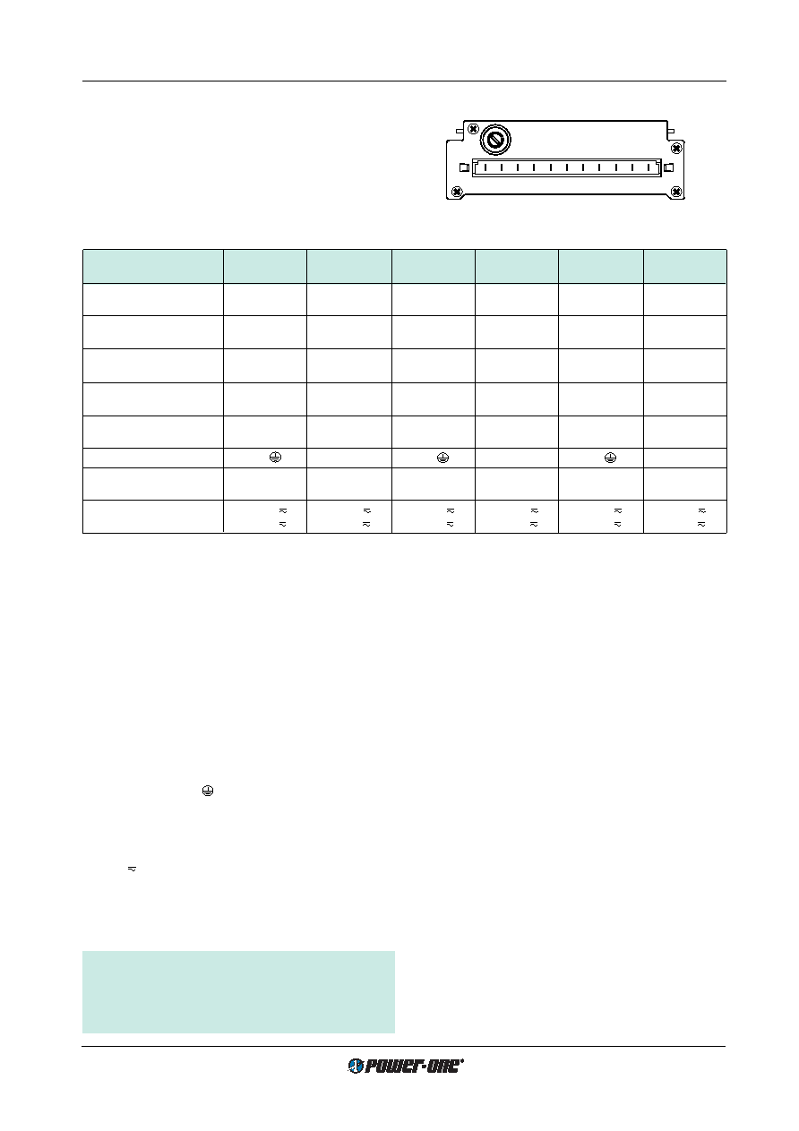
Connector Pin Allocation
The connector pin allocation table defines the electrical
potentials and the physical pin positions on the H11 con-
nector. Pin no. 26, the protective earth pin present on all
AM…LM (class I equipment) DC-DC converters is leading,
ensuring that it makes contact with the female connector
first.
32 29 26 23 20 17 14 11 85 2
10015
Fig. 17
View of male H11 connector.
Installation Instructions
The M series DC-DC converters are components, intended
exclusively for inclusion within other equipment by an in-
dustrial assembly operation or by professional installers. In-
stallation must strictly follow the national safety regulations
in compliance with the enclosure, mounting, creepage,
clearance, casualty, markings and segregation require-
ments of the end-use application. See also:
Technical Infor-
mation: Installation and Application.
Connection to the system shall be made via the female con-
nector H11 (see
Accessories). Other installation methods
may not meet the safety requirements.
AM...LM DC-DC converters (class I equipment) are pro-
vided with pin no. 26 (
), which is reliably connected with
their case. For safety reasons it is essential to connect this
pin with the protective earth of the supply system if required
in:
Safety of operator accessible output circuit .
An input fuse is built-in in the connection from pin no. 32
(Vi– or P ) of the unit. Since this fuse is designed to protect
the unit in case of an overcurrent and does not necessarily
cover all customer needs, an external fuse suitable for the
application and in compliance with the local requirements
might be necessary in the wiring to one or both input pins
(no. 29 and/or no. 32).
Important: Whenever the inhibit function is not in use,
pin 2 (i) should be connected to pin 23 (Vo1–) to enable
the output(s).
Do not open the modules, or guarantee will be invali-
dated.
Make sure that there is sufficient air flow possible for con-
vection cooling. This should be verified by measuring the
case temperature when the unit is installed and operated in
the end-use application. The maximum specified case tem-
perature
TC max shall not be exceeded. See also: Thermal
Considerations.
If the end-product is to be UL certified, the temperature of
the main isolation transformer should be evaluated as part
of the end-product investigation.
Protection Degree
Condition: Female connector fitted to the unit.
IP 40: All units, except those with options P, A or K, and
except those with option D or V with potentiometer.
IP 30: All units fitted with options A or K, except those with
option P, and except those with option D or V with
potentiometer.
IP 20: All units fitted with option P, or with option D or V with
potentiometer.
Cleaning Agents
In order to avoid possible damage, any penetration of liq-
uids (e.g. cleaning fluids) is to be prevented, since the
power supplies are not hermetically sealed.
相关PDF资料 |
PDF描述 |
|---|---|
| CMZ1301-7PV2 | 1-OUTPUT 50 W DC-DC REG PWR SUPPLY MODULE |
| CMZ1301-7RAF | 1-OUTPUT 50 W DC-DC REG PWR SUPPLY MODULE |
| CMZ1301-9PV3 | 1-OUTPUT 50 W DC-DC REG PWR SUPPLY MODULE |
| CMZ1301-9PV3AHF | 1-OUTPUT 50 W DC-DC REG PWR SUPPLY MODULE |
| CMZ1501-7PV3 | 1-OUTPUT 50 W DC-DC REG PWR SUPPLY MODULE |
相关代理商/技术参数 |
参数描述 |
|---|---|
| CMZ14(TE12L,L,X) | 制造商:Toshiba America Electronic Components 功能描述:CMZ14(TE12L,L,X) - Tape and Reel |
| CMZ14(TE12L,L,X,M) | 制造商:Toshiba America Electronic Components 功能描述:CMZ14(TE12L,L,X,M) - Tape and Reel |
| CMZ15 | 制造商:TOSHIBA 制造商全称:Toshiba Semiconductor 功能描述:Constant Voltage Regulation Transient Suppressors |
| CMZ15(TE12L,Q) | 功能描述:稳压二极管 Diode Zener 15V 2W RoHS:否 制造商:Vishay Semiconductors 齐纳电压:12 V 电压容差:5 % 电压温度系数:0.075 % / K 齐纳电流: 功率耗散:3 W 最大反向漏泄电流:3 uA 最大齐纳阻抗:7 Ohms 最大工作温度:+ 150 C 安装风格:SMD/SMT 封装 / 箱体:DO-214AC 封装:Reel |
| CMZ15(TE12L,Q,M) | 功能描述:稳压二极管 15V 2W M-FLAT RoHS:否 制造商:Vishay Semiconductors 齐纳电压:12 V 电压容差:5 % 电压温度系数:0.075 % / K 齐纳电流: 功率耗散:3 W 最大反向漏泄电流:3 uA 最大齐纳阻抗:7 Ohms 最大工作温度:+ 150 C 安装风格:SMD/SMT 封装 / 箱体:DO-214AC 封装:Reel |
发布紧急采购,3分钟左右您将得到回复。