- 您现在的位置:买卖IC网 > PDF目录223608 > COP8SGR928V7 (National Semiconductor Corporation) 8-Bit CMOS ROM Based and OTP Microcontrollers with 8k to 32k Memory, Two Comparators and USART PDF资料下载
参数资料
| 型号: | COP8SGR928V7 |
| 厂商: | National Semiconductor Corporation |
| 英文描述: | 8-Bit CMOS ROM Based and OTP Microcontrollers with 8k to 32k Memory, Two Comparators and USART |
| 中文描述: | 8位的CMOS基于ROM和OTP微控制器具有8K到32K的内存,2个比较器和USART |
| 文件页数: | 30/62页 |
| 文件大小: | 913K |
| 代理商: | COP8SGR928V7 |
第1页第2页第3页第4页第5页第6页第7页第8页第9页第10页第11页第12页第13页第14页第15页第16页第17页第18页第19页第20页第21页第22页第23页第24页第25页第26页第27页第28页第29页当前第30页第31页第32页第33页第34页第35页第36页第37页第38页第39页第40页第41页第42页第43页第44页第45页第46页第47页第48页第49页第50页第51页第52页第53页第54页第55页第56页第57页第58页第59页第60页第61页第62页
10.0 Interrupts (Continued)
ample, if the Software Trap routine is located at 0310 Hex,
then the vector location 0yFE and -0yFF should contain the
data 03 and 10 Hex, respectively. When a Software Trap
interrupt occurs and the VIS instruction is executed, the
program jumps to the address specified in the vector table.
The interrupt sources in the vector table are listed in order of
rank, from highest to lowest priority. If two or more enabled
and pending interrupts are detected at the same time, the
one with the highest priority is serviced first. Upon return
from the interrupt service routine, the next highest-level
pending interrupt is serviced.
If the VIS instruction is executed, but no interrupts are en-
abled and pending, the lowest-priority interrupt vector is
used, and a jump is made to the corresponding address in
the vector table. This is an unusual occurrence, and may be
the result of an error. It can legitimately result from a change
in the enable bits or pending flags prior to the execution of
the VIS instruction, such as executing a single cycle instruc-
tion which clears an enable flag at the same time that the
pending flag is set. It can also result, however, from inad-
vertent execution of the VIS command outside of the context
of an interrupt.
The default VIS interrupt vector can be useful for applica-
tions in which time critical interrupts can occur during the
servicing of another interrupt. Rather than restoring the pro-
gram context (A, B, X, etc.) and executing the RETI instruc-
tion, an interrupt service routine can be terminated by return-
ing to the VIS instruction. In this case, interrupts will be
serviced in turn until no further interrupts are pending and
the default VIS routine is started. After testing the GIE bit to
ensure that execution is not erroneous, the routine should
restore the program context and execute the RETI to return
to the interrupted program.
This technique can save up to fifty instruction cycles (t
c), or
more, (50s at 10 MHz oscillator) of latency for pending
interrupts with a penalty of fewer than ten instruction cycles
if no further interrupts are pending.
To ensure reliable operation, the user should always use the
VIS instruction to determine the source of an interrupt. Al-
though it is possible to poll the pending bits to detect the
source of an interrupt, this practice is not recommended. The
use of polling allows the standard arbitration ranking to be
altered, but the reliability of the interrupt system is compro-
mised. The polling routine must individually test the enable
and pending bits of each maskable interrupt. If a Software
Trap interrupt should occur, it will be serviced last, even
though it should have the highest priority. Under certain
conditions, a Software Trap could be triggered but not ser-
viced, resulting in an inadvertent “locking out” of all
maskable interrupts by the Software Trap pending flag.
Problems such as this can be avoided by using VIS
instruction.
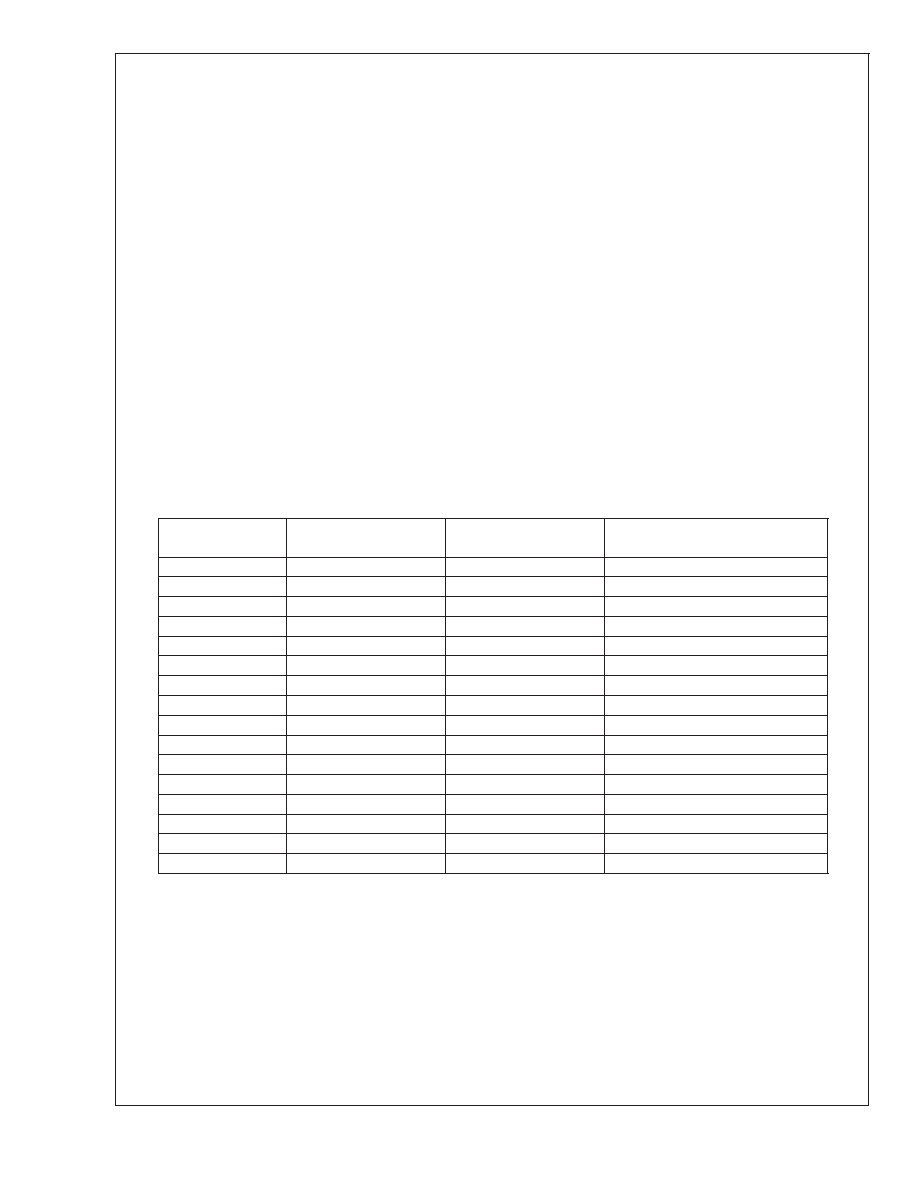
TABLE 6. Interrupt Vector Table
Arbitration Ranking
Source
Description
Vector Address (Note 17)
(Hi-Low Byte)
(1) Highest
Software
INTR Instruction
0yFE–0yFF
(2)
Reserved
0yFC–0yFD
(3)
External
G0
0yFA–0yFB
(4)
Timer T0
Underflow
0yF8–0yF9
(5)
Timer T1
T1A/Underflow
0yF6–0yF7
(6)
Timer T1
T1B
0yF4–0yF5
(7)
MICROWIRE/PLUS
BUSY Low
0yF2–0yF3
(8)
Reserved
0yF0–0yF1
(9)
USART
Receive
0yEE–0yEF
(10)
USART
Transmit
0yEC–0yED
(11)
Timer T2
T2A/Underflow
0yEA–0yEB
(12)
Timer T2
T2B
0yE8–0yE9
(13)
Timer T3
T2A/Underflow
0yE6–0yE7
(14)
Timer T3
T3B
0yE4–0yE5
(15)
Port L/Wakeup
Port L Edge
0yE2–0yE3
(16) Lowest
Default VIS
Reserved
0yE0–0yE1
Note 17: y is a variable which represents the VIS block. VIS and the vector table must be located in the same 256-byte block except if VIS is located at the last
address of a block. In this case, the table must be in the next block.
COP8SG
Family
www.national.com
36
相关PDF资料 |
PDF描述 |
|---|---|
| COP8SGR928V8 | 8-Bit CMOS ROM Based and OTP Microcontrollers with 8k to 32k Memory, Two Comparators and USART |
| COP8SGR928V9 | 8-Bit CMOS ROM Based and OTP Microcontrollers with 8k to 32k Memory, Two Comparators and USART |
| COPCSH984XXX/WM | 8-BIT, MROM, 10 MHz, MICROCONTROLLER, PDSO28 |
| CP-8-D-2-TS1-TP | INTERCONNECTION DEVICE |
| CP2-SAB1100#NAME | TWO PART BOARD CONNECTOR |
相关代理商/技术参数 |
参数描述 |
|---|---|
| COP8-SKFLASH-00 | 功能描述:开发板和工具包 - 其他处理器 DEV STARTER KIT RoHS:否 制造商:Freescale Semiconductor 产品:Development Systems 工具用于评估:P3041 核心:e500mc 接口类型:I2C, SPI, USB 工作电源电压: |
| COP8-SKFLASH-01 | 功能描述:开发板和工具包 - 其他处理器 COP8 5V FLASH STARTER KIT RoHS:否 制造商:Freescale Semiconductor 产品:Development Systems 工具用于评估:P3041 核心:e500mc 接口类型:I2C, SPI, USB 工作电源电压: |
| COP8-SW-COP8C | 制造商:NSC 制造商全称:National Semiconductor 功能描述:8-Bit CMOS Flash Microcontroller with 8k Memory, Dual Op Amps, Virtual EEROM, Temperature Sensor,10-Bit A/D and Brownout Reset |
| COP8-SW-COP8CW | 制造商:NSC 制造商全称:National Semiconductor 功能描述:8-Bit CMOS Flash Microcontroller with 8k Memory, Dual Op Amps, Virtual EEROM, Temperature Sensor,10-Bit A/D and Brownout Reset |
| COP8-SW-EWCOP8 | 制造商:NSC 制造商全称:National Semiconductor 功能描述:8-Bit CMOS Flash Microcontroller with 8k Memory, Dual Op Amps, Virtual EEROM, Temperature Sensor,10-Bit A/D and Brownout Reset |
发布紧急采购,3分钟左右您将得到回复。