- 您现在的位置:买卖IC网 > PDF目录15876 > CP2101EK (Silicon Laboratories Inc)KIT DEVELOPMENT RS232 TO USB PDF资料下载
参数资料
| 型号: | CP2101EK |
| 厂商: | Silicon Laboratories Inc |
| 文件页数: | 4/20页 |
| 文件大小: | 0K |
| 描述: | KIT DEVELOPMENT RS232 TO USB |
| 标准包装: | 1 |
| 其它名称: | 336-1076 CP2101EK-ND Q1572300 |
CP2101
12
Rev. 1.8
5. USB Function Controller and Transceiver
The Universal Serial Bus function controller in the CP2101 is a USB 2.0 compliant full-speed device with
integrated transceiver and on-chip matching and pull-up resistors. The USB function controller manages
all data transfers between the USB and the UART as well as command requests generated by the USB
host controller and commands for controlling the function of the UART.
The USB Suspend and Resume signals are supported for power management of both the CP2101 device
as well as external circuitry. The CP2101 will enter Suspend mode when Suspend signaling is detected
on the bus. On entering Suspend mode, the CP2101 asserts the SUSPEND and SUSPEND signals.
SUSPEND and SUSPEND are also asserted after a CP2101 reset until device configuration during USB
Enumeration is complete
The CP2101 exits the Suspend mode when any of the following occur: (1) Resume signaling is detected or
generated, (2) a USB Reset signal is detected, or (3) a device reset occurs. On exit of Suspend mode, the
SUSPEND and SUSPEND signals are de-asserted.
Both SUSPEND and SUSPEND temporarily float high during a CP2101 reset. If this behavior is undesir-
able, a strong pulldown (10 k
) can be used to ensure SUSPEND remains low during reset. See
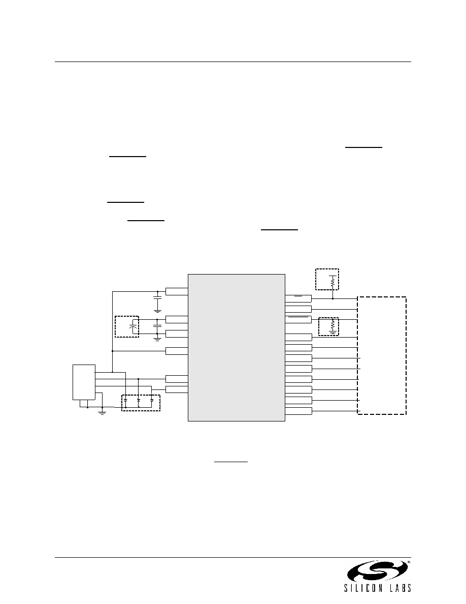
Figure 5.1 for other recommended options.
Option 1: A 4.7 k
pull-up resistor can be added to increase noise immunity.
Option 2: A 4.7
F capacitor can be added if powering other devices from the on-chip regulator.
Option 3: Avalanche transient voltage suppression diodes can be added for ESD protection.
Option 3: Use Littlefuse p/n SP0503BAHT or equivalent.
Option 4: 10 k
resistor to ground to hold SUSPEND low on initial power on or device reset.
1
CP2101
SUSPEND
11
12
REGIN
7
GND
3
RST
9
D+
4
D-
5
8
C2
0.1
F
C1
1
F
RI
DCD
CTS
RTS
RXD
TXD
DSR
DTR
2
1
28
27
26
25
24
23
2
3
External RS-232
transceiver or
UART circuitry
(to external circuitry
for USB suspend
states)
VBUS
D-
D+
GND 4
5
6
USB
CONNECTOR
6
VDD
VBUS
VDD
R1
4.7 k
D1
D2
D3
Option 1
R2
10 k
Option 4
Option 3
C4
4.7
F
Option 2
Figure 5.1. Typical Connection Diagram
6. Asynchronous Serial Data Bus (UART) Interface
The CP2101 UART interface consists of the TX (transmit) and RX (receive) data signals as well as the
RTS, CTS, DSR, DTR, DCD and RI control signals. The UART supports RTS/CTS, DSR/DTR and X-On/X-
Off handshaking.
相关PDF资料 |
PDF描述 |
|---|---|
| HMC07DREN | CONN EDGECARD 14POS .100 EYELET |
| EMC12DRYH | CONN EDGECARD 24POS .100 EXTEND |
| ECC25DRXI | CONN EDGECARD 50POS DIP .100 SLD |
| RP15-4812SAW/N-HC | CONV DC/DC 15W 18-75VIN 12VOUT |
| EBC30DRAI | CONN EDGECARD 60POS R/A .100 SLD |
相关代理商/技术参数 |
参数描述 |
|---|---|
| CP2101GM | 制造商: 功能描述: 制造商:AVNET 功能描述: 制造商:undefined 功能描述: |
| CP2101-GM | 功能描述:输入/输出控制器接口集成电路 USB TO UART BRIDGE RoHS:否 制造商:Silicon Labs 产品: 输入/输出端数量: 工作电源电压: 最大工作温度:+ 85 C 最小工作温度:- 40 C 安装风格:SMD/SMT 封装 / 箱体:QFN-64 封装:Tray |
| CP2101-GMR | 功能描述:输入/输出控制器接口集成电路 USB TO UART BRIDGE RoHS:否 制造商:Silicon Labs 产品: 输入/输出端数量: 工作电源电压: 最大工作温度:+ 85 C 最小工作温度:- 40 C 安装风格:SMD/SMT 封装 / 箱体:QFN-64 封装:Tray |
| CP2101R | 功能描述:输入/输出控制器接口集成电路 USB to UART Bridge RoHS:否 制造商:Silicon Labs 产品: 输入/输出端数量: 工作电源电压: 最大工作温度:+ 85 C 最小工作温度:- 40 C 安装风格:SMD/SMT 封装 / 箱体:QFN-64 封装:Tray |
| CP2102 | 功能描述:输入/输出控制器接口集成电路 USE 634-CP2102-GM RoHS:否 制造商:Silicon Labs 产品: 输入/输出端数量: 工作电源电压: 最大工作温度:+ 85 C 最小工作温度:- 40 C 安装风格:SMD/SMT 封装 / 箱体:QFN-64 封装:Tray |
发布紧急采购,3分钟左右您将得到回复。