- 您现在的位置:买卖IC网 > PDF目录1908 > CP2120-GM (Silicon Laboratories Inc)IC I/O EXPANDER I2C/SPI 8B 20QFN PDF资料下载
参数资料
| 型号: | CP2120-GM |
| 厂商: | Silicon Laboratories Inc |
| 文件页数: | 5/24页 |
| 文件大小: | 0K |
| 描述: | IC I/O EXPANDER I2C/SPI 8B 20QFN |
| 产品培训模块: | CP21xx USB Bridge |
| 标准包装: | 91 |
| 接口: | I²C,SPI |
| 输入/输出数: | 8 |
| 中断输出: | 是 |
| 频率 - 时钟: | 400kHz |
| 电源电压: | 3 V ~ 3.6 V |
| 工作温度: | -40°C ~ 85°C |
| 安装类型: | 表面贴装 |
| 封装/外壳: | 20-VFQFN 裸露焊盘 |
| 供应商设备封装: | 20-QFN(4x4) |
| 包装: | 管件 |
| 产品目录页面: | 627 (CN2011-ZH PDF) |
| 其它名称: | 336-1324 |
CP2120
Rev. 0.4
13
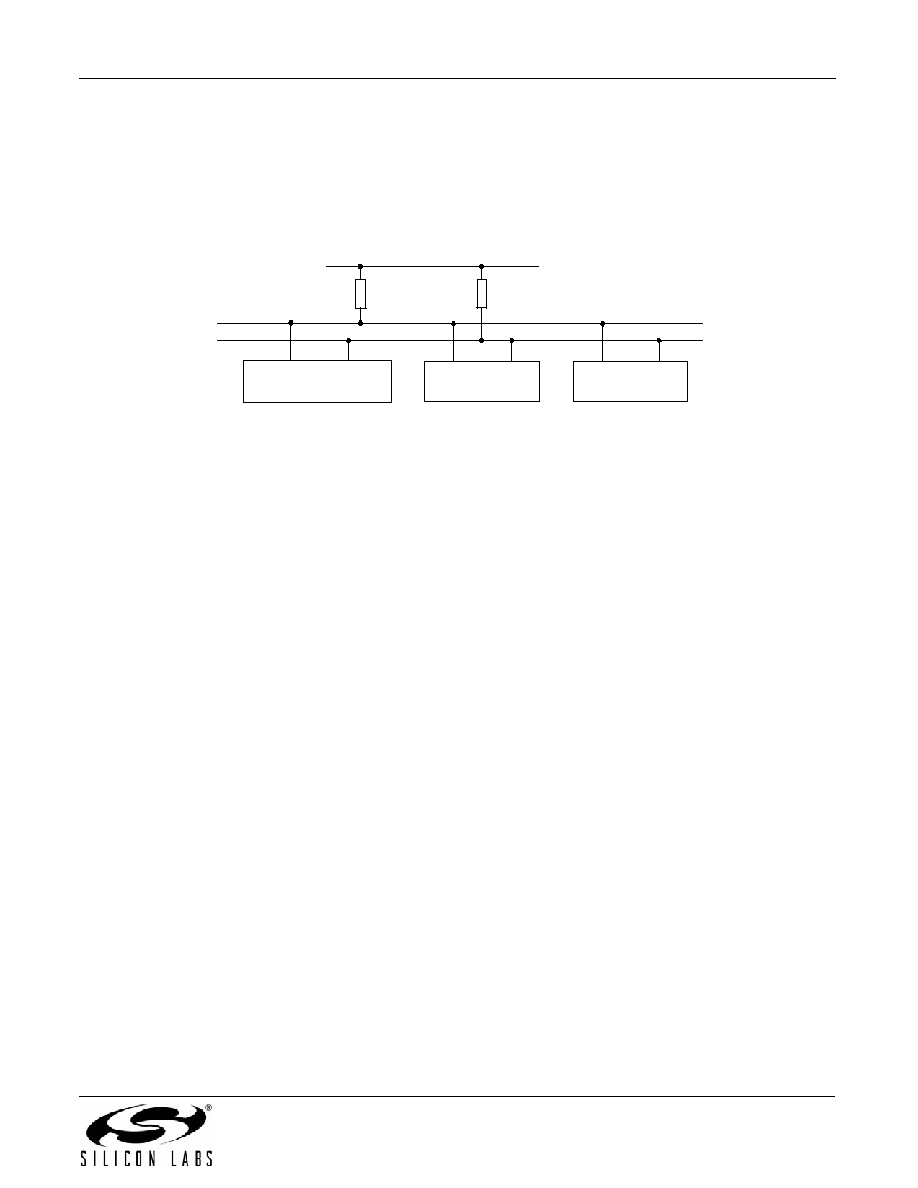
6. I2C Serial Interface
The CP2120 provides an I2C interface able to transfer data at frequencies up to 400 kHz. During a transaction, the
CP2120, operating as the I2C master, sources a data clock on the SCL pin as data travels across the bidirectional
SDA pin to and from an I2C slave device. The I2C interface lines each require a pull-up resistor. Figure 5 shows a
typical I2C bus.
Figure 5. Typical I2C Bus*
*Note: VDD is defined in Table 1, “Absolute Maximum Ratings,” on page 4. For Rpu values, please see “6.1.
6.1. Determining Pull-Up Register Values
Logic low to logic high transitions on the SCL and SDA pins, which are configured to open-drain output with
external pull-ups to VDD, take the form of an exponential curve with an RC time constant, where C equals the
capacitance of the bus and R equals the pull-up resistor value. I2C specification defines rise time as the time
required for a signal level to change from Vmin +0.15 V to Vmax-0.15 V. By solving the exponential equation using
a Vmin of 0 V and a Vmax of 3.3 V, the following equation can be used to find values for pull-up resistors:
Rise time = 3.04448 RC
Bus capacitance is governed by a number of factors, including signal trace length and capacitance introduced by
devices on the bus. 8 mm PCB signal traces on a two-layer board generally add 1 pF of capacitance per
centimeter of trace length. To determine the amount of capacitance introduced to the bus by I2C devices, consult
those devices’ datasheets. The maximum capacitance allowed before the bus violates I2C specification is 400 pF.
Rise time requirements vary depending on each connected I2C device’s timing requirements and the SCL clock
frequency. The maximum rise time allowed by the I2C specification is 1000 ns.
6.2. I2C Internal Registers
Features of the I2C interface are configured through the CP2120's Internal Registers. SCL clock frequency is set
by writing to the I2CCLK Internal Register. The frequency can be determined using the equation below. The I2C
frequency configured by the I2CCLOCK register is only an approximate frequency. Actual I2C frequencies can vary
due to conditions on the bus, such as a slave device extending the SCL low time.
Equation 1. I2C Clock Frequency
IC-BUS Device
CP2120
IC-BUS DEVICE
VDD
RpU
IC-bus
SDA
SCL
I
2
C Clock Frequency (kHz)
2000
I
2
CCLK
---------------------
=
相关PDF资料 |
PDF描述 |
|---|---|
| CP2200-GQ | IC ETH CTRLR SNGL-CHIP 48TQFP |
| CP80C86-2Z | IC CPU 16BIT 5V 8MHZ 40-PDIP |
| CP82C50A-5Z | IC ASYNC COMM ELEMENT UART 40DIP |
| CP82C89 | IC ARBITER BUS 5V 8MHZ 20-DIP |
| CPC1465D | IC DC TERMINATION 16-SOIC |
相关代理商/技术参数 |
参数描述 |
|---|---|
| CP2120-GMR | 功能描述:接口 - 专用 SPI-I2C BRIDGE & GPIO PORT EXPANDER RoHS:否 制造商:Texas Instruments 产品类型:1080p60 Image Sensor Receiver 工作电源电压:1.8 V 电源电流:89 mA 最大功率耗散: 最大工作温度:+ 85 C 安装风格:SMD/SMT 封装 / 箱体:BGA-59 |
| CP2-127-06L | 制造商:未知厂家 制造商全称:未知厂家 功能描述:Analog IC |
| CP2-127-06L-1-RTV-W6 | 制造商:Laird Technologies Inc 功能描述: |
| CP2-127-06LT | 制造商:未知厂家 制造商全称:未知厂家 功能描述:Analog IC |
| CP2-127-06TL | 制造商:未知厂家 制造商全称:未知厂家 功能描述:Analog IC |
发布紧急采购,3分钟左右您将得到回复。