参数资料
| 型号: | CP80C88Z |
| 厂商: | Intersil |
| 文件页数: | 4/38页 |
| 文件大小: | 0K |
| 描述: | IC PWM CONTROLLER |
| 标准包装: | 99 |
| 处理器类型: | 80C88 8/16-位 |
| 速度: | 5MHz |
| 电压: | 4.5 ~ 5.5V |
| 安装类型: | 通孔 |
| 封装/外壳: | 40-DIP(0.600",15.24mm) |
| 供应商设备封装: | 40-DIP |
| 包装: | 管件 |
第1页第2页第3页当前第4页第5页第6页第7页第8页第9页第10页第11页第12页第13页第14页第15页第16页第17页第18页第19页第20页第21页第22页第23页第24页第25页第26页第27页第28页第29页第30页第31页第32页第33页第34页第35页第36页第37页第38页
12
FN2949.4
February 22, 2008
Designers familiar with the 8085 or upgrading an 8085
design should note that the 8085 addresses I/O with an 8-bit
address on both halves of the 16-bit address bus. The
80C88 uses a full 16-bit address on its lower 16 address
lines.
External Interface
Processor Reset and Initialization
Processor initialization or start up is accomplished with
activation (HIGH) of the RESET pin. The 80C88 RESET is
required to be HIGH for greater than four clock cycles. The
80C88 will terminate operations on the high-going edge of
RESET and will remain dormant as long as RESET is HIGH.
The low-going transition of RESET triggers an internal reset
sequence for approximately 7 clock cycles. After this interval
the 80C88 operates normally, beginning with the instruction
in absolute location FFFFOH (see Figure 2). The RESET
input is internally synchronized to the processor clock. At
initialization, the HIGH to LOW transition of RESET must
occur no sooner than 50
μs after power up, to allow complete
initialization of the 80C88.
NMI will not be recognized if asserted prior to the second
CLK cycle following the end of RESET.
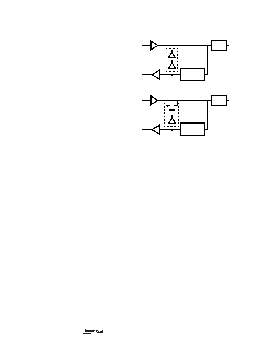
Bus Hold Circuitry
To avoid high current conditions caused by floating inputs to
CMOS devices and to eliminate the need for pull-up/down
resistors, “bus-hold” circuitry has been used on 80C88 pins
circuits maintain a valid logic state if no driving source is
present (i.e., an unconnected pin or a driving source which
goes to a high impedance state).
To override the “bus hold” circuits, an external driver must be
capable of supplying 400
μA minimum sink or source current
at valid input voltage levels. Since this “bus hold” circuitry is
active and not a “resistive” type element, the associated
power supply current is negligible. Power dissipation is
significantly reduced when compared to the use of passive
pull-up resistors.
Interrupt Operations
Interrupt operations fall into two classes: software or
hardware initiated. The software initiated interrupts and
software aspects of hardware interrupts are specified in the
instruction set description. Hardware interrupts can be
classified as nonmusical or maskable.
Interrupts result in a transfer of control to a new program
location. A 256 element table containing address pointers to
the interrupt service program locations resides in absolute
locations 0 through 3FFH (see Figure 2), which are reserved
for this purpose. Each element in the table is 4-bytes in size
and corresponds to an interrupt “type”. An interrupting
device supplies an 8-bit type number, during the interrupt
acknowledge sequence, which is used to vector through the
appropriate element to the new interrupt service program
location.
Non-Maskable Interrupt (NMI)
The processor provides a single non-maskable interrupt
(NMI) pin which has higher priority than the maskable
interrupt request (INTR) pin. A typical use would be to
activate a power failure routine. The NMI is edge-triggered
on a LOW to High transition. The activation of this pin
causes a type 2 interrupt.
NMI is required to have a duration in the HIGH state of
greater than two clock cycles, but is not required to be
synchronized to the clock. An high going transition of NMI is
latched on-chip and will be serviced at the end of the current
instruction or between whole moves (2-bytes in the case of
word moves) of a block type instruction. Worst case
response to NMI would be for multiply, divide, and variable
shift instructions. There is no specification on the occurrence
of the low-going edge; it may occur before, during, or after
the servicing of NMI. Another high-going edge triggers
another response if it occurs after the start of the NMI
procedure.
The signal must be free of logical spikes in general and be
free of bounces on the low-going edge to avoid triggering
extraneous responses.
Maskable Interrupt (INTR)
The 80C88 provides a singe interrupt request input (INTR)
which can be masked internally by software with the
resetting of the interrupt enable (IF) flag bit. The interrupt
request signal is level triggered. It is internally synchronized
during each clock cycle on the high-going edge of CLK.
FIGURE 6A. BUS HOLD CIRCUITRY PINS 2-16 AND 35-39
FIGURE 6B. BUS HOLD CIRCUITRY PINS 26-32 AND 34
FIGURE 6.
OUTPUT
DRIVER
INPUT
BUFFER
INPUT
PROTECTION
CIRCUITRY
BOND
PAD
EXTERNAL
PIN
OUTPUT
DRIVER
INPUT
BUFFER
INPUT
PROTECTION
CIRCUITRY
BOND
PAD
EXTERNAL
PIN
P
VCC
80C88
相关PDF资料 |
PDF描述 |
|---|---|
| CP80C88-2Z | IC PWM CONTROLLER |
| AYF331335 | CONN FPC 13POS .3MM SMD |
| MPC8314ECVRAFDA | MPU POWERQUICC II PRO 620-PBGA |
| MPC8313ZQAFFB | MPU POWERQUICC II PRO 516-PBGA |
| MPC8313CZQADDB | MPU POWERQUICC II PRO 516-PBGA |
相关代理商/技术参数 |
参数描述 |
|---|---|
| CP80S53 | 制造商:未知厂家 制造商全称:未知厂家 功能描述:EPROM/ROM-Based 8-Bit Microcontroller Series CP80S53A可替代PIC12C508/509 |
| CP80S53A | 制造商:未知厂家 制造商全称:未知厂家 功能描述:EPROM/ROM-Based 8-Bit Microcontroller Series CP80S53A可替代PIC12C508/509 |
| CP80S54 | 制造商:未知厂家 制造商全称:未知厂家 功能描述:EPROM/ROM-Based 8-Bit Microcontroller Series |
| CP80S54E | 制造商:未知厂家 制造商全称:未知厂家 功能描述:EPROM/ROM-Based 8-Bit Microcontroller Series |
| CP80S56 | 制造商:未知厂家 制造商全称:未知厂家 功能描述:EPROM/ROM-Based 8-Bit Microcontroller Series |
发布紧急采购,3分钟左右您将得到回复。