- 您现在的位置:买卖IC网 > PDF目录26507 > CPV363M4KPBF (VISHAY SEMICONDUCTORS) Trans IGBT Module N-CH 600V 11A 13-Pin IMS-2 PDF资料下载
参数资料
| 型号: | CPV363M4KPBF |
| 厂商: | VISHAY SEMICONDUCTORS |
| 元件分类: | 电源模块 |
| 英文描述: | Trans IGBT Module N-CH 600V 11A 13-Pin IMS-2 |
| 中文描述: | IGBT Transistors 600 Volt 6.0 Amp |
| 文件页数: | 1/11页 |
| 文件大小: | 246K |
| 代理商: | CPV363M4KPBF |
CPV363M4KPbF
www.vishay.com
Vishay Semiconductors
Revision: 11-Jun-13
1
Document Number: 94485
For technical questions within your region: DiodesAmericas@vishay.com, DiodesAsia@vishay.com, DiodesEurope@vishay.com
THIS DOCUMENT IS SUBJECT TO CHANGE WITHOUT NOTICE. THE PRODUCTS DESCRIBED HEREIN AND THIS DOCUMENT
ARE SUBJECT TO SPECIFIC DISCLAIMERS, SET FORTH AT www.vishay.com/doc?91000
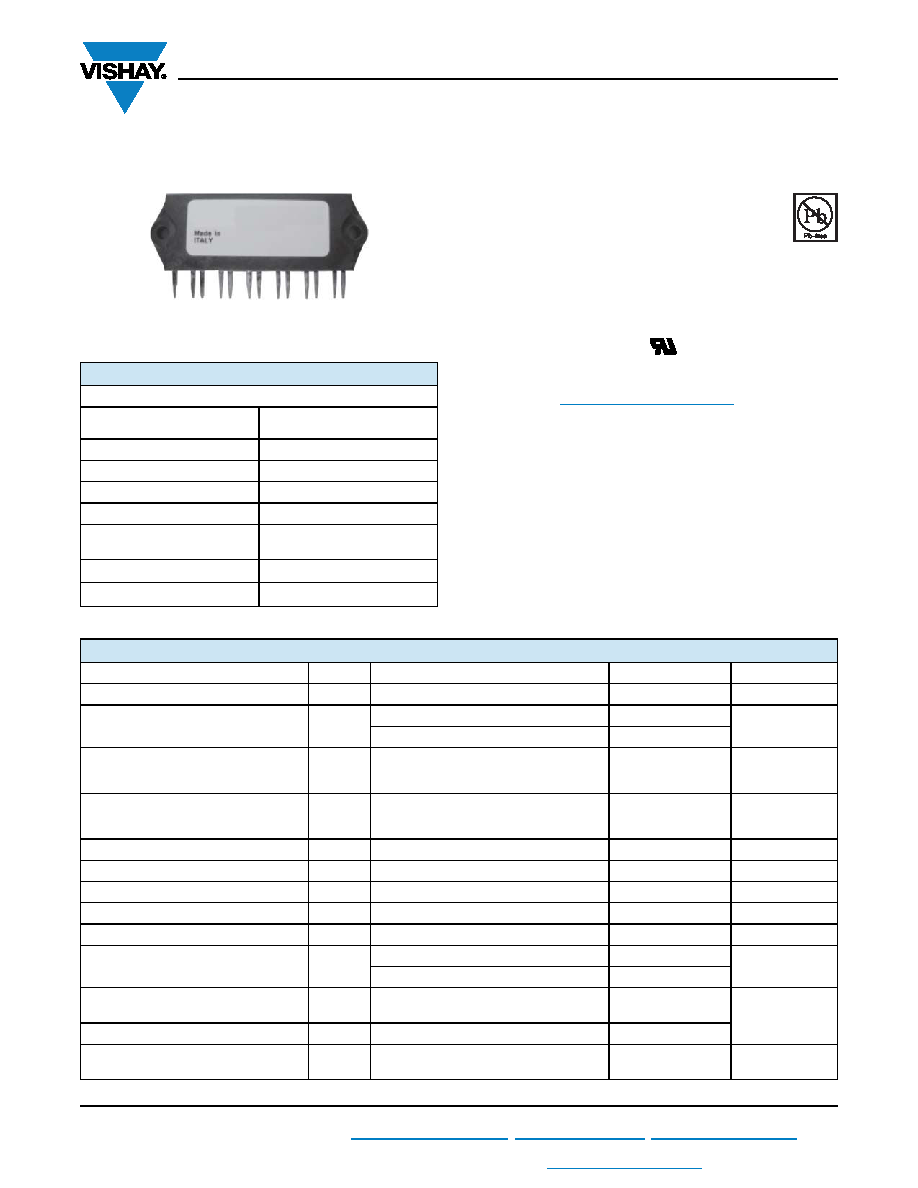
IGBT SIP Module
(Short Circuit Rated Ultrafast IGBT)
FEATURES
Short circuit rated ultrafast: Optimized for high
speed over 5.0 kHz (see fig. 1 for current vs.
frequency curve), and short circuit rated to 10 μs
at 125 °C, VGE = 15 V
Fully isolated printed circuit board mount
package
Switching-loss rating includes all “tail” losses
HEXFRED soft ultrafast diodes
UL approved file E78996
Designed and qualified for industrial level
Material categorization: For definitions of compliance
please see www.vishay.com/doc?99912
DESCRIPTION
The IGBT technology is the key to Vishay’s Semiconductors
advanced line of IMS (Insulated Metal Substrate) power
modules.
These
modules
are
more
efficient
than
comparable bipolar transistor modules, while at the same
time having the simpler gate-drive requirements of the
familiar power MOSFET. This superior technology has now
been coupled to a state of the art materials system that
maximizes power throughput with low thermal resistance.
This package is highly suited to motor drive applications and
where space is at a premium.
PRODUCT SUMMARY
OUTPUT CURRENT IN A TYPICAL 20 kHz MOTOR DRIVE
IRMS per phase (1.94 kW total)
with TC = 90 °C
6.7 ARMS
TJ
125 °C
Supply voltage
360 VDC
Power factor
0.8
Modulation depth (see fig. 1)
115 %
VCE(on) (typical)
at IC = 6.0 A, 25 °C
1.72 V
Package
SIP
Circuit
Three Phase Inverter
IMS-2
RoHS
COMPLIANT
ABSOLUTE MAXIMUM RATINGS
PARAMETER
SYMBOL
TEST CONDITIONS
MAX.
UNITS
Collector to emitter voltage
VCES
600
V
Continuous collector current, each IGBT
IC
TC = 25 °C
11
A
TC = 100 °C
6.0
Pulsed collector current
ICM
Repetitive rating; VGE = 20 V, pulse width
limited by maximum junction temperature
See fig. 20
22
A
Clamped inductive load current
ILM
VCC = 80 % (VCES), VGE = 20 V,
L = 10 μH, RG = 22
See fig. 19
22
A
Diode continuous forward current
IF
TC = 100 °C
6.1
A
Diode maximum forward current
IFM
22
A
Short circuit withstand time
tSC
10
μs
Gate to emitter voltage
VGE
± 20
V
Isolation voltage
VISOL
Any terminal to case, t = 1 minute
2500
VRMS
Maximum power dissipation, each IGBT
PD
TC = 25 °C
36
W
TC = 100 °C
14
Operating junction and
storage temperature range
TJ, TStg
- 40 to + 150
°C
Soldering temperature
For 10 s, (0.063" (1.6 mm) from case)
300
Mounting torque
6-32 or M3 screw
5 to 7
(0.55 to 0.8)
lbf
in
(N
m)
相关PDF资料 |
PDF描述 |
|---|---|
| CPV363M4UPBF | Trans IGBT Module N-CH 600V 11A 13-Pin IMS-2 |
| CPV364M4FPBF | Trans IGBT Module N-CH 600V 27A 13-Pin IMS-2 |
| CPV364M4KPBF | Trans IGBT Module N-CH 600V 24A 13-Pin IMS-2 |
| CPV364M4UPBF | Trans IGBT Module N-CH 600V 20A 13-Pin IMS-2 |
| CR02A-2240 | |
相关代理商/技术参数 |
参数描述 |
|---|---|
| CPV363M4U | 功能描述:IGBT SIP MODULE 600V 6.8A IMS-2 RoHS:否 类别:半导体模块 >> IGBT 系列:- 标准包装:10 系列:GenX3™ IGBT 类型:PT 配置:单一 电压 - 集电极发射极击穿(最大):600V Vge, Ic时的最大Vce(开):1.4V @ 15V,100A 电流 - 集电极 (Ic)(最大):430A 电流 - 集电极截止(最大):100µA Vce 时的输入电容 (Cies):31nF @ 25V 功率 - 最大:1000W 输入:标准 NTC 热敏电阻:无 安装类型:底座安装 封装/外壳:SOT-227-4,miniBLOC 供应商设备封装:SOT-227B |
| CPV363M4UPBF | 制造商:VISHAY 制造商全称:Vishay Siliconix 功能描述:IGBT SIP Module (Ultrafast IGBT) |
| CPV363MF | 制造商:IRF 制造商全称:International Rectifier 功能描述:IGBT SIP MODULE Fast IGBT |
| CPV363MK | 制造商:IRF 制造商全称:International Rectifier 功能描述:IGBT SIP MODULE Short Circuit Rated UltraFast IGBT |
| CPV363MM | 制造商:IRF 制造商全称:International Rectifier 功能描述:IGBT SIP MODULE Short Circuit Rated Fast IGBT |
发布紧急采购,3分钟左右您将得到回复。