- 您现在的位置:买卖IC网 > PDF目录169797 > CQ1001-9P 1-OUTPUT 82 W DC-DC REG PWR SUPPLY MODULE PDF资料下载
参数资料
| 型号: | CQ1001-9P |
| 元件分类: | 电源模块 |
| 英文描述: | 1-OUTPUT 82 W DC-DC REG PWR SUPPLY MODULE |
| 封装: | METAL, CASE Q01, MODULE |
| 文件页数: | 2/25页 |
| 文件大小: | 747K |
| 代理商: | CQ1001-9P |
Cassette Style
DC-DC Converters
Q Series
Edition 5/5.2000
10/25
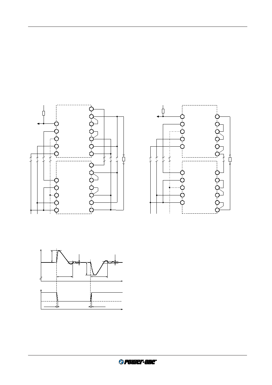
Parallel or Series Connection of Outputs and/or Units
Single or double output units with equal nominal output volt-
age can be connected in parallel without any precaution by
interconnecting the T-pins for approximate equal current
sharing. (See:
Auxiliary Functions.)
Any double output unit with its outputs in parallel behaves
like a single output unit, i.e. is fully regulated. There is no
inconvenience or restriction using the R-input and the
sense lines .
Single output units and/or main and second outputs of dou-
ble output units can be connected in series with any other
(similar) output. For double output modules consider, that
the effect via sense lines, R-input or option P is doubled.
load
Vo1+ (Vo2+)
Vo1–
Vo1– (Vo2–)
S–
S+
Vo1+
Single (double)
output
T
Vi–
Vi+
i
Out OK –
Out OK+
Vo1+ (Vo2+)
Vo1–
Vo1– (Vo2–)
S–
S+
Vo1+
Single (double)
output
T
Vi–
Vi+
i
Out OK –
Out OK+
+
i
+
–
Rp
05091
load
Vo1+
Vo2–
Vo1–
S–
S+
Vo2+
Double output
Vi–
Vi+
i
Out OK –
Out OK+
Vi–
Vi+
i
Out OK –
Out OK+
+
i
+
–
Vo1+
Vo2–
Vo1–
S–
S+
Vo2+
Double output
Rp
05092
Fig. 8
Parallel connection of outputs and/or several modules,
sense lines connected at connector side
Fig. 9
Series connection of outputs and/or several modules,
sense lines connected at connector side only
Note:
– Parallel connection of several double output units should
always include both, main and second output to maintain
good regulation of all outputs.
– Series connection of second outputs without involving
their main outputs should be avoided as regulation may
be poor.
– The maximum output current is limited by the output with
the lowest current limitation if several outputs are con-
nected in series.
– Rated output voltages above 48 V (SELV = Safety Extra
Low Voltage) need additional measures in order to com-
ply with international safety requirements.
Uod
td
Uo ±1%
t
≥10 s
Uo
0
0.5
1
Io/Io nom
05102
Dynamic Load Regulation
Fig. 10
Control deviation of Uo versus dynamic load change
Hold up Time
The modules provide virtually no hold up time. If hold up
time is required, use external output capacitors or decou-
pling diodes and input capacitors of adequate size.
Formula for additional external input capacitor
2
Po th 100
Ci ext = –––––––––––––––
h (Uti 2 – Ui min2)
where as:
Ci ext = external input capacitance [mF]
Po
= output power [W]
h
= efficiency [%]
th
= hold-up time [ms]
Ui min = minimum input voltage [V]
Uti
= threshold level [V]
相关PDF资料 |
PDF描述 |
|---|---|
| DQ2320-7P | 2-OUTPUT 96 W DC-DC REG PWR SUPPLY MODULE |
| EQ1101-9 | 1-OUTPUT 60 W DC-DC REG PWR SUPPLY MODULE |
| BQ1001-7R | 1-OUTPUT 82 W DC-DC REG PWR SUPPLY MODULE |
| EQ2660-7P | 2-OUTPUT 106 W DC-DC REG PWR SUPPLY MODULE |
| CQ92M | epoxy molded silicon Triacs |
相关代理商/技术参数 |
参数描述 |
|---|---|
| CQ1001-9R | 功能描述:EURO-CASSETTE 82W 5.1V RoHS:否 类别:电源 - 外部/内部(非板载) >> DC DC Converters 系列:* 标准包装:1 系列:Quint 类型:隔离 输入电压:24V 输出:24V 输出数:1 输出 - 1 @ 电流(最大):24 VDC @ 50A 输出 - 2 @ 电流(最大):- 输出 - 3 @ 电流(最大):- 输出 - 4 @ 电流(最大):- 功率(瓦特):1200W 安装类型:底座安装 工作温度:0°C ~ 40°C 效率:- 封装/外壳:模块 尺寸/尺寸:4.33" L x 9.09" W x 6.14" H(110mm x 231mm x 156mm) 包装:散装 电源(瓦特)- 最大:1200W 批准:- 其它名称:277-69722866365-NDQUINT-BAT/24DC/12AH |
| CQ1001-9RG | 功能描述:DC/DC CONVERT 5.1V 20A 制造商:bel power solutions 系列:* 零件状态:有效 标准包装:5 |
| CQ10663001 | 功能描述:CABLE STRANDED 制造商:te connectivity raychem cable protection 系列:* 零件状态:有效 标准包装:1 |
| CQ10A1KB394K3 | 制造商:ARIZONA 功能描述:CAPACITOR MILITARY FILM 制造商:DEARBORN ELECTRONICS INC 功能描述:CAPACITOR MILITARY FILM |
| CQ10A1KC224K3 | 制造商: 功能描述: 制造商:undefined 功能描述: |
发布紧急采购,3分钟左右您将得到回复。