- 您现在的位置:买卖IC网 > PDF目录380066 > CS4215-KL (CIRRUS LOGIC INC) 16-Bit Multimedia Audio Codec PDF资料下载
参数资料
| 型号: | CS4215-KL |
| 厂商: | CIRRUS LOGIC INC |
| 元件分类: | 消费家电 |
| 英文描述: | 16-Bit Multimedia Audio Codec |
| 中文描述: | SPECIALTY CONSUMER CIRCUIT, PQCC44 |
| 封装: | PLASTIC, LCC-44 |
| 文件页数: | 9/52页 |
| 文件大小: | 878K |
| 代理商: | CS4215-KL |
第1页第2页第3页第4页第5页第6页第7页第8页当前第9页第10页第11页第12页第13页第14页第15页第16页第17页第18页第19页第20页第21页第22页第23页第24页第25页第26页第27页第28页第29页第30页第31页第32页第33页第34页第35页第36页第37页第38页第39页第40页第41页第42页第43页第44页第45页第46页第47页第48页第49页第50页第51页第52页
1 V
rms
. The CMOUT reference level is used to
level shift the signal. This level shifting allows
the line inputs to be DC coupled into the
CS4215. Minimum ADC offset results when the
line inputs are DC coupled (see Analog Charac-
teristics Table).
Figure 3 shows an AC coupled input circuit for
signals centered around 0 Volts. The anti-alias-
ing RC filter presents a low impedance at high
frequencies and should be driven by a low im-
pedance source.
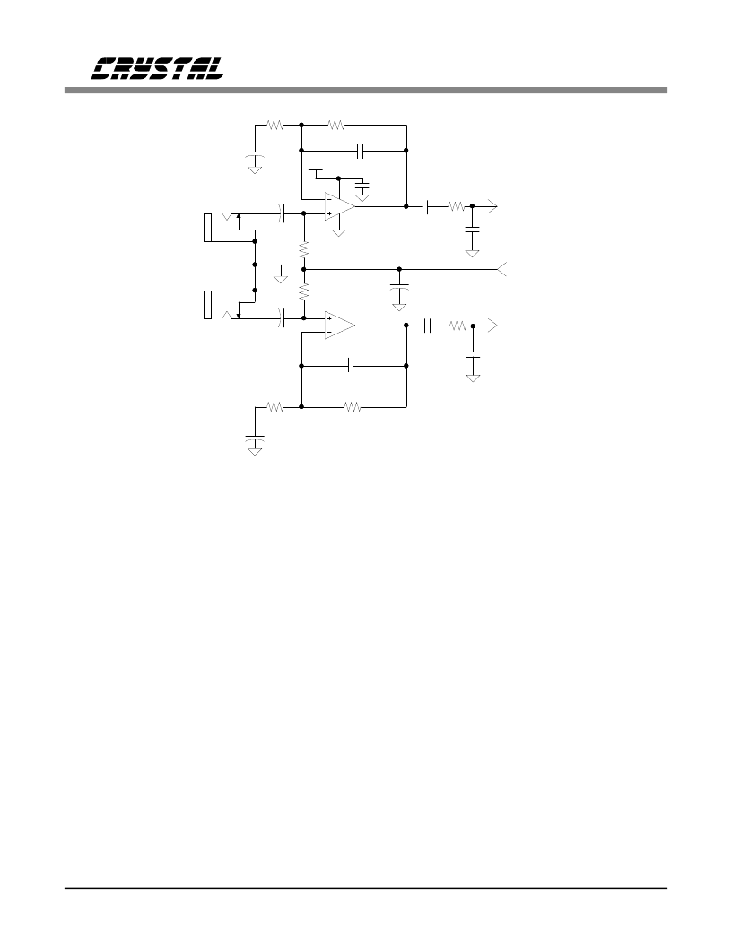
Microphone Level Inputs
Internal amplifiers with a programmable 20 dB
gain block are provided for the microphone level
inputs, MINR and MINL. Figure 4 shows a sin-
gle-ended input microphone pre-amplifier stage
with a gain of 23 dB. AC coupling is mandatory
for these inputs since any DC offset on the input
will be amplified by the codec.
The 20 dB gain block may be disabled using the
MLB bit in Control Time Slot 1. When
dis-
abled, the inputs become line level with full
scale inputs of 1 Vrms.
Adjustable Input Gain
The signals from the microphone or the line in-
puts are routed to a programmable gain circuit
which provides up to 22.5 dB of gain in 1.5 dB
steps. Level changes only take effect on zero
crossings to minimize audible artifacts, often re-
ferred to as "zipper noise". The requested level
change is forced if no zero crossing is found af-
ter 511 frames (10.6 ms at a 48 kHz frame rate).
A separate zero crossing detector exists for each
channel.
Analog Outputs
The analog outputs of the DACs are routed via
an attenuator to a pair of line outputs, a pair of
MINR
1 uF
C6
+
C5
2
3
VA+
8
0.1 uF
C4
560 pF
NPO
10 uF
+
R6
2.2 k
R4
22.1 k
4
1 uF
+
R5
50 k
MINL
(Mono)
1 uF
+
C2
6
5
C1
560 pF
R3
2.2 k
R1
22.1 k
150
10 uF
+
R2
50 k
NPO
C3
CMOUT
C47
C8
1
7
R57
U2
MC33078 or
MC33178
C7
C46
A =20 dB
0.47 uF
C48
0.01 uF
NPO
150
R56
0.01 uF
NPO
Microphone
Input Left
(pin 17)
Microphone
Input Right
(pin 15)
0.47 uF
C45
Figure 4. Optional Microphone Input Buffer
CS4215
DS76F2
9
相关PDF资料 |
PDF描述 |
|---|---|
| CS4215-KQ | 16-Bit Multimedia Audio Codec |
| CS4215 | 16-Bit Multimedia Audio Codec |
| CS4216 | 16-Bit Stereo Audio Codec |
| CS4216-KL | IC EEPROM SRL 256-8BIT 8DIP |
| CS4216-KQ | 16-Bit Stereo Audio Codec |
相关代理商/技术参数 |
参数描述 |
|---|---|
| CS4215-KL-ES | 制造商:CRYSTAL 功能描述: |
| CS4215-KQ | 制造商:CIRRUS 制造商全称:Cirrus Logic 功能描述:16-Bit Multimedia Audio Codec |
| CS4216 | 制造商:CIRRUS 制造商全称:Cirrus Logic 功能描述:16-Bit Stereo Audio Codec |
| CS4216-KL | 制造商:Rochester Electronics LLC 功能描述:- Bulk |
| CS4216-KQ | 制造商:CIRRUS 制造商全称:Cirrus Logic 功能描述:16-Bit Stereo Audio Codec |
发布紧急采购,3分钟左右您将得到回复。