- 您现在的位置:买卖IC网 > PDF目录380066 > CS4215 (Cirrus Logic, Inc.) 16-Bit Multimedia Audio Codec PDF资料下载
参数资料
| 型号: | CS4215 |
| 厂商: | Cirrus Logic, Inc. |
| 元件分类: | Codec |
| 英文描述: | 16-Bit Multimedia Audio Codec |
| 中文描述: | 16位多媒体音频编解码器 |
| 文件页数: | 21/52页 |
| 文件大小: | 878K |
| 代理商: | CS4215 |
第1页第2页第3页第4页第5页第6页第7页第8页第9页第10页第11页第12页第13页第14页第15页第16页第17页第18页第19页第20页当前第21页第22页第23页第24页第25页第26页第27页第28页第29页第30页第31页第32页第33页第34页第35页第36页第37页第38页第39页第40页第41页第42页第43页第44页第45页第46页第47页第48页第49页第50页第51页第52页
DATA MODE
The data mode is used during conversions to
pass digital data between the CS4215 and exter-
nal devices. The frame sync rate is equal to the
value of the conversion frequency set by the
DFR2-DFR0 bits of the Data Format register.
Each frame has either 64, 128, or 256 bit times
depending on the BSEL bits in the Serial Con-
trol register. Control of gain, attenuation, input
selection and output muting are embedded in the
data stream.
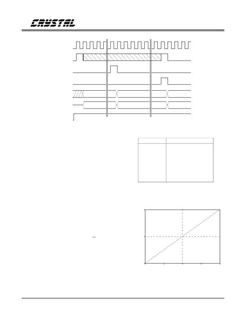
Data Formats
All time slots contain 8 bits. The MSB of the
data is transmitted/received first. The CS4215
data registers have the functions and time slot as-
signments shown in Table 2. The register address
is the time slot number when D/C is 1. The
SDOUT pin goes into a high-impedance state
prior to time slot 1 and after Time Slot 8 (see
Figure 12).
The CS4215 supports four audio data formats:
16-bit 2’s-complement linear, 8-bit unsigned lin-
ear, 8-bit A-Law, and 8-bit
μ
-Law. Figure 13
illustrates the transfer characteristic for 16-bit
and 8-bit linear formats. Note that a digital code
SCLK
1
2
64
128
2
65 66
1
TSOUT B
SDIN
D/C
_
Data to A
Data to B
Data to A
3
4
67 68
3
4
FSYNC,
TSIN A
TSOUT A,
TSIN B
128
69
Data from A
Data from B
Data from A
SDOUT
Data Mode
Figure 12. Data Mode Timing for 2 CS4215’s
0
+FS
-FS
A
0
65
128
191
255
DIGITAL CODE
8-bit
unsigned:
2’16-bit
-16384
0
16384
32767
Figure 13. Linear Data Formats
Time slot
1
2
3
4
5
6
7
8
Description
Left Audio MS8 bits
Left Audio LS8 bits
Right Audio MS8 bits
Right Audio LS8 bits
Output Setting
Output Setting
Input Setting
Input Setting
Table 2. Data Registers
CS4215
DS76F2
21
相关PDF资料 |
PDF描述 |
|---|---|
| CS4216 | 16-Bit Stereo Audio Codec |
| CS4216-KL | IC EEPROM SRL 256-8BIT 8DIP |
| CS4216-KQ | 16-Bit Stereo Audio Codec |
| CS4218-KL | 16-Bit Stereo Audio Codec |
| CS4218-KQ | 16-Bit Stereo Audio Codec |
相关代理商/技术参数 |
参数描述 |
|---|---|
| CS4215-KL | 制造商:Rochester Electronics LLC 功能描述:- Bulk |
| CS4215-KL-ES | 制造商:CRYSTAL 功能描述: |
| CS4215-KQ | 制造商:CIRRUS 制造商全称:Cirrus Logic 功能描述:16-Bit Multimedia Audio Codec |
| CS4216 | 制造商:CIRRUS 制造商全称:Cirrus Logic 功能描述:16-Bit Stereo Audio Codec |
| CS4216-KL | 制造商:Rochester Electronics LLC 功能描述:- Bulk |
发布紧急采购,3分钟左右您将得到回复。