- 您现在的位置:买卖IC网 > PDF目录13689 > CS51411EMNR2G (ON Semiconductor)IC REG BUCK 1.5A 18DFN PDF资料下载
参数资料
| 型号: | CS51411EMNR2G |
| 厂商: | ON Semiconductor |
| 文件页数: | 13/20页 |
| 文件大小: | 0K |
| 描述: | IC REG BUCK 1.5A 18DFN |
| 标准包装: | 2,500 |
| 类型: | 降压(降压) |
| 输出数: | 1 |
| 输入电压: | 4.5 V ~ 40 V |
| PWM 型: | 混合物 |
| 频率 - 开关: | 260kHz |
| 电流 - 输出: | 1.5A |
| 同步整流器: | 无 |
| 工作温度: | -40°C ~ 85°C |
| 安装类型: | 表面贴装 |
| 封装/外壳: | 18-VFDFN 裸露焊盘 |
| 包装: | 带卷 (TR) |
| 供应商设备封装: | 18-DFN(5x6) |
�� �
�
�CS51411,� CS51412,� CS51413,� CS51414�
�turns� P1� on� and� current� is� routed� to� the� internal� bias� circuitry�
�from� the� BIAS� pin.�
�Here� is� an� example� of� the� power� savings:�
�The� input� voltage� range� for� V� in� is� 4.5� V� to� 40� V.� The� input�
�voltage� range� for� BIAS� is� 3.3� V� to� 6� V.� The� quiescent� current�
�specification� is� 3� mA� (min),� 4� mA� (typ),� and� 6.25� mA� (max).�
�Using� a� typical� battery� voltage� of� 14� V� and� the� typical�
�quiescent� current� number� of� 4� mA,� the� power� would� be:�
�P� +� V�
�I� +� 14�
�4e� ?� 3� +� 56� mW�
�We’ll� assume� the� BIAS� pin� is� connected� to� an� external�
�regulator� at� 5� V� instead� of� the� output� voltage.� The� BIAS� pin�
�would� normally� be� connected� to� the� output� voltage,� but�
�adding� an� added� switching� regulator� efficiency� number� here�
�would� cloud� this� example.� Now� the� internal� BIAS� circuitry�
�is� being� powered� via� 5� V.� The� resulting� on� chip� power� being�
�dissipated� is:�
�P� +� V� I� +� 5� 4e� ?� 3� +� 21� mW�
�The� power� savings� is� 35� mW.�
�Now,� to� demonstrate� more� notable� savings� using� the�
�maximum� battery� input� voltage� of� 40� V,� the� maximum�
�quiescent� current� of� 6.25� mA,� and� the� lowest� allowed� BIAS�
�voltage� for� proper� operation� of� 3.3� V;�
�Powered� from� V� in� :�
�P� +� 40� 6.25e� ?� 3� +� 250� mW�
�Powered� from� the� BIAS� pin:�
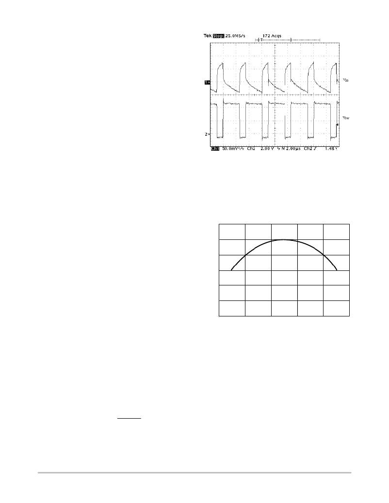
�Figure� 19.� Input� Voltage� Ripple� in� a� Buck� Converter�
�To� calculate� the� RMS� current,� multiply� the� load� current�
�with� the� constant� given� by� Figure� 20� at� each� duty� cycle.� It� is�
�a� common� practice� to� select� the� input� capacitor� with� an� RMS�
�current� rating� more� than� half� the� maximum� load� current.� If�
�multiple� capacitors� are� paralleled,� the� RMS� current� for� each�
�capacitor� should� be� the� total� current� divided� by� the� number�
�of� capacitors.�
�0.6�
�P� +� 3.3�
�6.25e� ?� 3� +� 21� mW�
�0.5�
�The� power� savings� is� 229� mW.�
�Minimum� Load� Requirement�
�As� pointed� out� in� the� previous� section,� a� minimum� load� is�
�required� for� this� regulator� due� to� the� predriver� current�
�feeding� the� output.� Placing� a� resistor� equal� to� V� O� divided� by�
�12� mA� should� prevent� any� voltage� overshoot� at� light� load�
�conditions.� Alternatively,� the� feedback� resistors� can� be�
�valued� properly� to� consume� 12� mA� current.�
�0.4�
�0.3�
�0.2�
�0.1�
�COMPONENT� SELECTION�
�0�
�0�
�0.2�
�0.4� 0.6�
�DUTY� CYCLE�
�0.8�
�1.0�
�Input� Capacitor�
�In� a� buck� converter,� the� input� capacitor� witnesses� pulsed�
�current� with� an� amplitude� equal� to� the� load� current.� This�
�pulsed� current� and� the� ESR� of� the� input� capacitors� determine�
�the� V� IN� ripple� voltage,� which� is� shown� in� Figure� 19.� For� V� IN�
�ripple,� low� ESR� is� a� critical� requirement� for� the� input�
�capacitor� selection.� The� pulsed� input� current� possesses� a�
�significant� AC� component,� which� is� absorbed� by� the� input�
�capacitors.�
�The� RMS� current� of� the� input� capacitor� can� be� calculated�
�using:�
�IRMS� +� IO� D(1� *� D)�
�where:�
�D� =� switching� duty� cycle� which� is� equal� to� V� O� /V� IN� .�
�I� O� =� load� current.�
�Figure� 20.� Input� Capacitor� RMS� Current� can� be�
�Calculated� by� Multiplying� Y� Value� with� Maximum� Load�
�Current� at� any� Duty� Cycle�
�Selecting� the� capacitor� type� is� determined� by� each�
�design’s� constraint� and� emphasis.� The� aluminum�
�electrolytic� capacitors� are� widely� available� at� lowest� cost.�
�Their� ESR� and� Equivalent� Series� Inductor� (ESL)� are�
�relatively� high.� Multiple� capacitors� are� usually� paralleled� to�
�achieve� lower� ESR.� In� addition,� electrolytic� capacitors�
�usually� need� to� be� paralleled� with� a� ceramic� capacitor� for�
�filtering� high� frequency� noises.� The� OS� ?� CON� are� solid�
�aluminum� electrolytic� capacitors,� and� therefore� has� a� much�
�lower� ESR.� Recently,� the� price� of� the� OS� ?� CON� capacitors�
�has� dropped� significantly� so� that� it� is� now� feasible� to� use�
�them� for� some� low� cost� designs.� Electrolytic� capacitors� are�
�http://onsemi.com�
�13�
�相关PDF资料 |
PDF描述 |
|---|---|
| MAX6323EUT29+T | IC SUPERVISOR 2.93V SOT23-6 |
| SC105-391 | INDUCTOR SMD 390UH 0.48A 1KHZ |
| 4448R-26L | TOROID POWER HI CURRENT 68UH SMD |
| SC105-180 | INDUCTOR SMD 18UH 2.15A 2.52MHZ |
| MAX6323DUT46+T | IC SUPERVISOR 4.63V SOT23-6 |
相关代理商/技术参数 |
参数描述 |
|---|---|
| CS51411EVB | 功能描述:电源管理IC开发工具 ANA CS51411/3 EVAL BOARD RoHS:否 制造商:Maxim Integrated 产品:Evaluation Kits 类型:Battery Management 工具用于评估:MAX17710GB 输入电压: 输出电压:1.8 V |
| CS51411GD8 | 功能描述:直流/直流开关调节器 1.5A Low Voltage RoHS:否 制造商:International Rectifier 最大输入电压:21 V 开关频率:1.5 MHz 输出电压:0.5 V to 0.86 V 输出电流:4 A 输出端数量: 最大工作温度: 安装风格:SMD/SMT 封装 / 箱体:PQFN 4 x 5 |
| CS51411GD8G | 功能描述:直流/直流开关调节器 1.5A Low Voltage Buck RoHS:否 制造商:International Rectifier 最大输入电压:21 V 开关频率:1.5 MHz 输出电压:0.5 V to 0.86 V 输出电流:4 A 输出端数量: 最大工作温度: 安装风格:SMD/SMT 封装 / 箱体:PQFN 4 x 5 |
| CS51411GDR8 | 功能描述:直流/直流开关调节器 1.5A Low Voltage RoHS:否 制造商:International Rectifier 最大输入电压:21 V 开关频率:1.5 MHz 输出电压:0.5 V to 0.86 V 输出电流:4 A 输出端数量: 最大工作温度: 安装风格:SMD/SMT 封装 / 箱体:PQFN 4 x 5 |
| CS51411GDR8G | 功能描述:直流/直流开关调节器 1.5A Low Voltage Buck RoHS:否 制造商:International Rectifier 最大输入电压:21 V 开关频率:1.5 MHz 输出电压:0.5 V to 0.86 V 输出电流:4 A 输出端数量: 最大工作温度: 安装风格:SMD/SMT 封装 / 箱体:PQFN 4 x 5 |
发布紧急采购,3分钟左右您将得到回复。