- 您现在的位置:买卖IC网 > PDF目录295335 > CS600/L2 (ISOCOM LTD) 1 CHANNEL LOGIC OUTPUT OPTOCOUPLER PDF资料下载
参数资料
| 型号: | CS600/L2 |
| 厂商: | ISOCOM LTD |
| 元件分类: | 光电耦合器 |
| 英文描述: | 1 CHANNEL LOGIC OUTPUT OPTOCOUPLER |
| 封装: | HERMETIC SEALED, CERAMIC PACKAGE-6 |
| 文件页数: | 2/12页 |
| 文件大小: | 561K |
| 代理商: | CS600/L2 |
For sales enquiries, or further information, please contact our sales office at:
Isocom Ltd, Hutton Close, Crowther Industrial Estate, District 3, Washington, NE38 0AH
Tel: +44 0191 4166 546 Fax: +44 0191 4155 055
2007 Copyright reserved to Isocom Limited
QC 88000-C004: 2007
Page 10 of 12
ISOCOMLTD
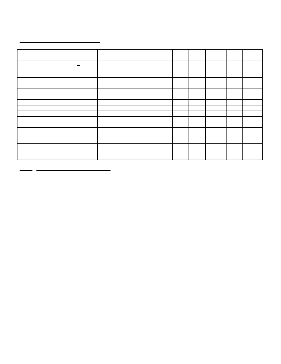
Typical Characteristics
TA = 25°C, VCC = 5V each channel where appropriate
Parameter
Symbol
Test Conditions
Note
s
Min
Type
Max
Units
Input Diode Temperature
Coefficient
VF
TA
IF = 20mA
1
-
-1.9
-
mV/°C
Resistance
RI-O
V10 = 500V
3
-
10
12
-
Capacitance
CI-O
f = 1MHz
3
-
1.9
-
pF
Input Capacitance
CIN
f = 1MHz, VF = 0
1
-
60
-
pF
Input-Input Leakage
Current
II-I
45% Relative Humidity
VII = 500Vdc, t = 5S
4
-
0.5
-
nA
Resistance
RI-I
VII = 500Vdc
4
-
10
12
-
Capacitance
CI-I
f = 1MHz
4
-
0.6
-
pF
Output Rise (10-90%)
tr
RL = 510, CL = 15pF, IF = 13mA
1
-
35
-
nS
Output Fall Time (90-
10%)
tf
RL = 510, CL = 15pF, IF = 13mA
1
-
35
-
nS
Common Mode Transient
Immunity at Logic High
Output Level
CMH
VO (min) = 2V, VCM = 10V (peak)
RL = 510, IF = 0mA
1 & 7
-
1000
-
V/S
Common Mode Transient
Immunity at Logic Low
Output Level
CML
VO(max) = 0.8V, VCM = 10V (peak)
RL = 510, IF = 10mA
1 & 8
-
-1000
-
V/S
Notes: (Apply typically to 16 pin package)
1. Each channel, where appropriate.
2. Measured between pins 1 through 4 shorted together, and pins 9 through 16 shorted together.
3. Measured between pins 1 and 2, or 5 and 6 shorted together, and pins 9 through 16 shorted together.
4. Measured between pins 1 and 2 shorted together, and pins 5 and 6 shorted together.
5. The tPLH propagation delay is measured from the 6.5mA point on the trailing edge of the input pulse to the 1.5V point
on the trailing edge of the output pulse.
6. The tPHL propagation delay is measured from the 6.5mA point on the leading edge of the input pulse to the 1.5V point
on the leading edge of the output pulse.
7. CMH is the maximum tolerable common mode transient to assure that the output will remain in a high logic state (i.e.,
VO > 2.0V).
8. CML is the maximum tolerable common mode transient to assure that the output will remain in the logic low state
(i.e., VO < 2.0V).
9. It is essential that a bypass capacitor (0.1 to 0.1F, ceramic) be connected from pin 10 to pin 15. Total lead length
between both ends of the capacitor and the isolator pins should not exceed 20mm.
10. This is a momentary withstand test, not an operating condition.
相关PDF资料 |
PDF描述 |
|---|---|
| CSBLA384KECE-B0 | CERAMIC RESONATOR, 0.384 MHz |
| CSC5026-0102F | 16 CONTACT(S), COMBINATION LINE CONNECTOR, SOCKET |
| CSD10030 | ZERO RECOVERY RECTIFIER |
| CSD10030A | ZERO RECOVERY RECTIFIER |
| CSD20120 | RECTIFIER |
相关代理商/技术参数 |
参数描述 |
|---|---|
| CS6010 | 制造商:未知厂家 制造商全称:未知厂家 功能描述: |
| CS60-100L | 制造商:Coilcraft Inc 功能描述:Current sensor, RoHS |
| CS601-23io1 | 制造商:n/a 功能描述:Thyristor |
| CS60-12io1 | 功能描述:SCR 60 Amps 1200V RoHS:否 制造商:STMicroelectronics 最大转折电流 IBO:480 A 额定重复关闭状态电压 VDRM:600 V 关闭状态漏泄电流(在 VDRM IDRM 下):5 uA 开启状态 RMS 电流 (It RMS): 正向电压下降:1.6 V 栅触发电压 (Vgt):1.3 V 最大栅极峰值反向电压:5 V 栅触发电流 (Igt):35 mA 保持电流(Ih 最大值):75 mA 安装风格:Through Hole 封装 / 箱体:TO-220 封装:Tube |
| CS60-14io1 | 功能描述:SCR 60 Amps 1400V RoHS:否 制造商:STMicroelectronics 最大转折电流 IBO:480 A 额定重复关闭状态电压 VDRM:600 V 关闭状态漏泄电流(在 VDRM IDRM 下):5 uA 开启状态 RMS 电流 (It RMS): 正向电压下降:1.6 V 栅触发电压 (Vgt):1.3 V 最大栅极峰值反向电压:5 V 栅触发电流 (Igt):35 mA 保持电流(Ih 最大值):75 mA 安装风格:Through Hole 封装 / 箱体:TO-220 封装:Tube |
发布紧急采购,3分钟左右您将得到回复。