- 您现在的位置:买卖IC网 > PDF目录170207 > CS8413-CS (Electronic Theatre Controls, Inc.) 96 KHZ DIGITAL AUDIO RECEIVER PDF资料下载
参数资料
| 型号: | CS8413-CS |
| 厂商: | Electronic Theatre Controls, Inc. |
| 英文描述: | 96 KHZ DIGITAL AUDIO RECEIVER |
| 中文描述: | 96 kHz的数字音频接收器 |
| 文件页数: | 9/38页 |
| 文件大小: | 646K |
| 代理商: | CS8413-CS |
第1页第2页第3页第4页第5页第6页第7页第8页当前第9页第10页第11页第12页第13页第14页第15页第16页第17页第18页第19页第20页第21页第22页第23页第24页第25页第26页第27页第28页第29页第30页第31页第32页第33页第34页第35页第36页第37页第38页
CS8413 CS8414
DS240F1
17
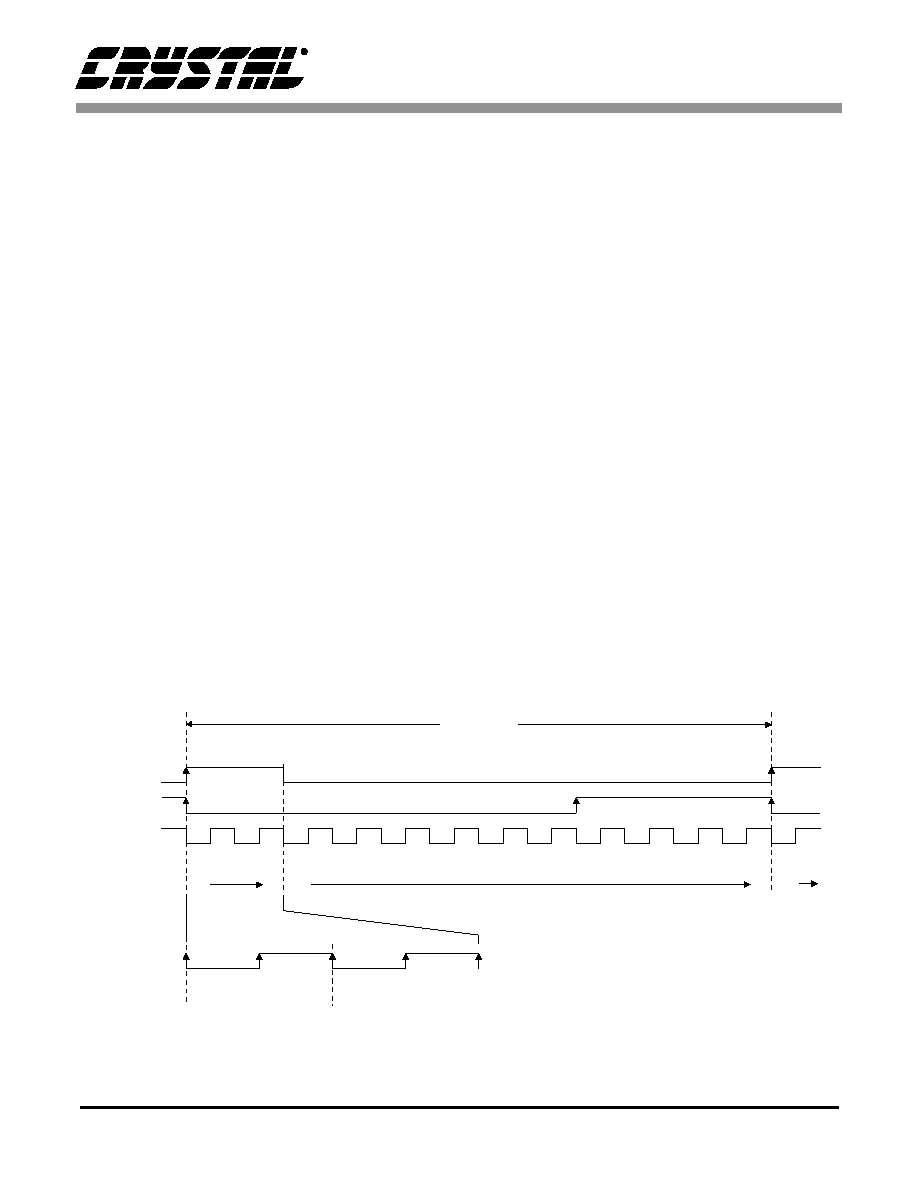
FLAG1 in status register 1, SR1, can be used to
monitor the channel status buffer. In mode 0,
FLAG1 is set low after channel status byte 23 (the
last byte) is written, and is set high when channel
status byte 15, location 17H is written. If the corre-
sponding interrupt enable bit in IER1 is set, a tran-
sition of FLAG1 will generate a pulse on the
interrupt pin. Figure 12 illustrates the memory
write sequence for buffer mode 0 along with flag
timing. The arrows on the flag timing indicate
when an interrupt will occur if the appropriate in-
terrupt enable bit is set. FLAG0 can cause an inter-
rupt on either edge, which is only shown in the
expanded portion of the figure for clarity.
Buffer Mode 1
In buffer mode 1, eight bytes are allocated for chan-
nel status data and sixteen bytes for auxiliary data
as shown in Figure 5. The user data buffer is the
same for all modes. The channel status buffer, loca-
tions 08H to 0FH, is divided into two sections. The
first four locations always contain the first four
bytes of channel status, identical to mode 0, and are
written once per channel status block. The second
four locations, addresses 0CH to 0FH, provide a
cyclic buffer for the last 20 bytes of channel status
data. The channel status buffer is divided in this
fashion because the first four bytes are the most im-
portant ones; whereas, the last 20 bytes are often
not used (except for byte 23, CRC).
FLAG1 and FLAG2 can be used to monitor this
buffer as shown in Figure 13. FLAG1 is set high
when CS byte 1, location 09H, is written and is tog-
gled when every other byte is written. FLAG2 is set
high after CS byte 23 is written and set low after CS
byte 3, location 0BH, is written. FLAG2 deter-
mines whether the channel status pointer is writing
to the first four-byte section of the channel status
buffer or the second four-byte section, while
FLAG1 indicates which two bytes of the section
are free to update.
The auxiliary data buffer, locations 10H to 1FH, is
written to in a cyclic manner similar to the other
buffers. Four auxiliary data bits are received per
audio sample (sub-frame) and, since the auxiliary
data is four times larger than the user data, the aux-
iliary data buffer on the CS8413 is four times larger
allowing FLAG0 to be used to monitor both.
FLAG0
FLAG1
FLAG2
(384 Audio Samples)
(Expanded)
Block
08
0B 0C
1F 08
C.S. Address
0
1
234
5
678
9
10 11 12 13 14 15 16 17 18 19 20 21 22 23 0
1
C.S. Byte
FLAG0
C.S. Addr.
User Addr.
(Addresses are in Hex)
04
05
06
07
04
05
06
07
08
09
0A
0B
1F
07
Figure 12. CS8413 Buffer Memory Write Sequence - MODE 0
相关PDF资料 |
PDF描述 |
|---|---|
| CS8414 | 96 KHZ DIGITAL AUDIO RECEIVER |
| CS8414-CS | 96 KHZ DIGITAL AUDIO RECEIVER |
| CSB7152-01 | 70 V, SILICON, PIN DIODE |
| CSBFB1M00J58-R1 | CERAMIC RESONATOR, 1 MHz |
| CSBLA400KECE-B0 | CERAMIC RESONATOR, 0.4 MHz |
相关代理商/技术参数 |
参数描述 |
|---|---|
| CS8413-CSR | 功能描述:音频 DSP IC 96 kHz Digital Audio Receivers RoHS:否 制造商:Texas Instruments 工作电源电压: 电源电流: 工作温度范围: 安装风格: 封装 / 箱体: 封装:Tube |
| CS8414 | 制造商:未知厂家 制造商全称:未知厂家 功能描述:96 KHZ DIGITAL AUDIO RECEIVER |
| CS8414CS | 制造商:CRYS 功能描述: 制造商:The Cherry Corporation 功能描述: |
| CS8414-CS | 制造商:Rochester Electronics LLC 功能描述: 制造商:Cirrus Logic 功能描述: |
| CS8414-CSR | 制造商:Rochester Electronics LLC 功能描述: 制造商:Cirrus Logic 功能描述: |
发布紧急采购,3分钟左右您将得到回复。