- 您现在的位置:买卖IC网 > PDF目录223611 > CS8442XN8 (ON SEMICONDUCTOR) STEPPER MOTOR CONTROLLER, PDIP8 PDF资料下载
参数资料
| 型号: | CS8442XN8 |
| 厂商: | ON SEMICONDUCTOR |
| 元件分类: | 运动控制电子 |
| 英文描述: | STEPPER MOTOR CONTROLLER, PDIP8 |
| 封装: | 0.300 INCH, PLASTIC, MS-001, DIP-8 |
| 文件页数: | 1/4页 |
| 文件大小: | 44K |
| 代理商: | CS8442XN8 |
1
Features
s
Buffered Speed Sensor
Output
s
No Cross-conduction in
either H-bridge
s
Guaranteed Monotonic
s
On Chip Flyback Diodes
s
Fault Protection
Overvoltage
Short Circuit Protection
Load Dump Protection
to 60V
Package Options
8 Lead PDIP
CS8442
Stepper Motor Driver
with Buffered Speed Signal Output
1
Gnd
COILA+
COILA–
SENSOR
IN
VCC
COILB+
COILB–
SENSOR
OUT
Description
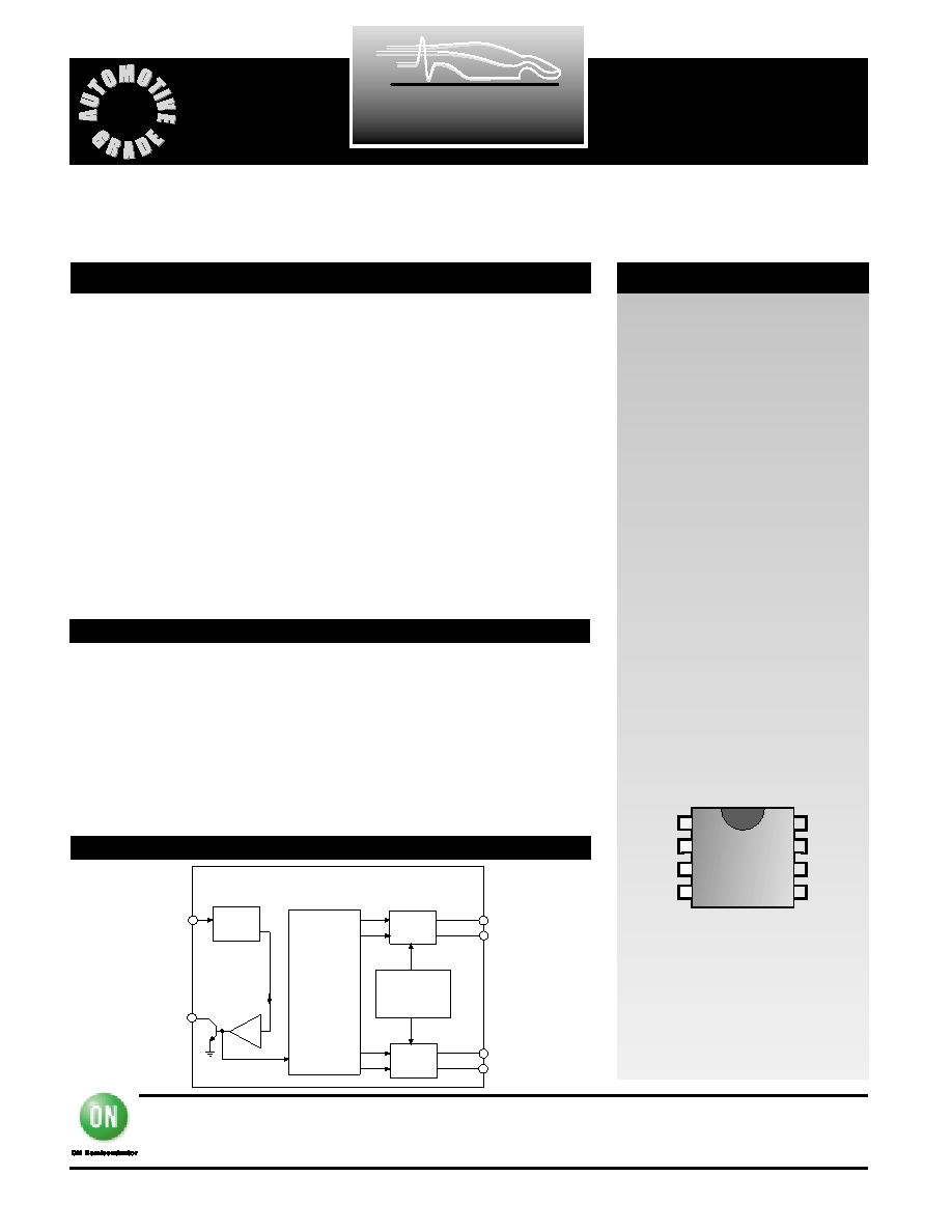
Block Diagram
Absolute Maximum Ratings
CS8442
December, 2001 - Rev. 2
ON Semiconductor
2000 South County Trail, East Greenwich, RI 02818
Tel: (401)885–3600 Fax: (401)885–5786
N. American Technical Support: 800-282-9855
Web Site: www.cherry–semi.com
ARCHIVE
DEVICE
NOT
RECOMMENDED
FOR
NEW
DESIGN
The CS8442 is a stepper motor
driver that implements an H-
bridge design to drive two coils in
an eight step sequence each revo-
lution. Each H-bridge is capable of
delivering 85mA to the load.
The sequencer function insures
that the odometer is monotonic
and that cross-conduction of each
H bridges does not occur. Before
the beginning of each sequence,
both bridges are turned off. This
“dead zone” minimizes the fly
back energy generated in the
inductive loads. In addition, on
board clamp diodes across each
output protect the output drive
transistors from excessive fly back
voltages.
The CS8442 is fault protected
against reverse battery, short cir-
cuit, and over voltage conditions.
If a fault is detected, the IC shuts
down.
The buffered speed signal output
(SENSOR OUT) is an open collec-
tor NPN capable of driving a
4.7k
load connected to a 5V sup-
ply. The signal is a buffered,
inverted version of the speed sen-
sor input voltage (SENSOR IN).
The input voltage can be either a
sine or square wave form.
Supply Voltage (VCC) (continuous) -40C to +105C ..................–0.5 to 24V
(100ms pulse transient) -40C to +105C ......................–0.5 to 60V
Input Voltage (VIN) ..............................................................–0.3 to VCC +0.3V
Storage Temperature Range (TSTG)......................................–65°C to +150°C
Junction Temperature.............................................................–40°C to +150°C
Speed Sensor Output .....................................................................................7V
ESD (Human Body Model) .........................................................................2kV
Lead Temperature Soldering
Wave Solder (through hole styles only) ........10 sec. max, 260°C peak
COILB-
SENSOR
IN
SENSOR
OUT
Coil
Driver
B
Coil
Driver
A
Overvoltage
and Short
Circuit
Protection
Sequencer
COILB+
COILA-
COILA+
Input
Comp.
相关PDF资料 |
PDF描述 |
|---|---|
| CS9ARH-FREQ1 | CRYSTAL OSCILLATOR, CLOCK, 50 MHz - 300 MHz, PECL OUTPUT |
| CS9TRH-FREQ2 | CRYSTAL OSCILLATOR, CLOCK, 300.001 MHz - 700 MHz, PECL OUTPUT |
| CS9ASH-FREQ1 | CRYSTAL OSCILLATOR, CLOCK, 50 MHz - 300 MHz, PECL OUTPUT |
| CS9AUH-FREQ1 | CRYSTAL OSCILLATOR, CLOCK, 50 MHz - 300 MHz, PECL OUTPUT |
| CS9AUH-FREQ2 | CRYSTAL OSCILLATOR, CLOCK, 300.001 MHz - 700 MHz, PECL OUTPUT |
相关代理商/技术参数 |
参数描述 |
|---|---|
| CS844A1 | 制造商:HVPSI 制造商全称:High Voltage Power Solutions, Inc. 功能描述:MOV Modules |
| CS844A2 | 制造商:HVPSI 制造商全称:High Voltage Power Solutions, Inc. 功能描述:MOV Modules |
| CS844B1 | 制造商:HVPSI 制造商全称:High Voltage Power Solutions, Inc. 功能描述:MOV Modules |
| CS844B2 | 制造商:HVPSI 制造商全称:High Voltage Power Solutions, Inc. 功能描述:MOV Modules |
| CS844C1 | 制造商:HVPSI 制造商全称:High Voltage Power Solutions, Inc. 功能描述:MOV Modules |
发布紧急采购,3分钟左右您将得到回复。