- 您现在的位置:买卖IC网 > PDF目录19192 > CUB7TVS0 (Red Lion Controls)TIMER LCD PROGRAM 8-DIGIT HV REF PDF资料下载
参数资料
| 型号: | CUB7TVS0 |
| 厂商: | Red Lion Controls |
| 文件页数: | 5/8页 |
| 文件大小: | 0K |
| 描述: | TIMER LCD PROGRAM 8-DIGIT HV REF |
| 标准包装: | 1 |
| 系列: | CUB7 |
| 工作模式: | 累积 |
| 输出类型: | 无 |
| 电源电压: | 不需要(包括电池) |
| 端接类型: | 导线引线 |
| 显示器类型: | LCD 无背光 |
| 产品目录页面: | 2853 (CN2011-ZH PDF) |
| 其它名称: | RLC135 |
�� �
�
�5.0� W� IRING� T� HE� M� ETER�
�WIRING� OVERVIEW�
�Electrical� connections� are� made� to� the� #22� AWG� colored� wires� protruding�
�from� the� rear� of� the� unit.� When� using� the� optional� terminal� block,� the� #22� AWG�
�colored� wires� are� cut� off� and� electrical� connections� are� made� via� screwless� type�
�terminal� block.� All� conductors� should� conform� to� the� meter� ’s� voltage� and�
�current� ratings.� All� cabling� and� wire� terminations� should� conform� to� appropriate�
�standards� of� good� installation,� local� codes� and� regulations.� It� is� recommended�
�that� the� backlight� power� supplied� to� the� meter� (DC� or� AC)� be� protected� by� a� fuse�
�or� circuit� breaker.�
�EMC� INSTALLATION� GUIDELINES�
�Although� this� meter� is� designed� with� a� high� degree� of� immunity� to� Electro-�
�Magnetic� Interference� (EMI),� proper� installation� and� wiring� methods� must� be�
�followed� to� ensure� compatibility� in� each� application.� The� type� of� the� electrical�
�noise,� source� or� coupling� method� into� the� meter� may� be� different� for� various�
�installations.� The� meter� becomes� more� immune� to� EMI� with� fewer� I/O�
�connections.� Cable� length,� routing,� and� shield� termination� are� very� important�
�and� can� mean� the� difference� between� a� successful� or� troublesome� installation.�
�Listed� below� are� some� EMC� guidelines� for� successful� installation� in� an�
�industrial� environment.�
�1.� The� meter� should� be� mounted� in� a� metal� enclosure,� which� is� properly�
�connected� to� protective� earth.�
�2.� Use� shielded� (screened)� cables� for� all� Signal� and� Control� inputs.� The� shield�
�(screen)� pigtail� connection� should� be� made� as� short� as� possible.� The�
�connection� point� for� the� shield� depends� somewhat� upon� the� application.�
�Listed� below� are� the� recommended� methods� of� connecting� the� shield,� in� order�
�of� their� effectiveness.�
�a.� Connect� the� shield� only� at� the� panel� where� the� unit� is� mounted� to� earth�
�ground� (protective� earth).�
�b.� Connect� the� shield� to� earth� ground� at� both� ends� of� the� cable,� usually� when�
�the� noise� source� frequency� is� above� 1� MHz.�
�c.� Connect� the� shield� to� common� of� the� meter� and� leave� the� other� end� of� the�
�shield� unconnected� and� insulated� from� earth� ground.�
�3.� Never� run� Signal� or� Control� cables� in� the� same� conduit� or� raceway� with� AC�
�power� lines,� conductors� feeding� motors,� solenoids,� SCR� controls,� and�
�heaters,� etc.� The� cables� should� be� ran� in� metal� conduit� that� is� properly�
�grounded.� This� is� especially� useful� in� applications� where� cable� runs� are� long�
�and� portable� two-way� radios� are� used� in� close� proximity� or� if� the� installation�
�is� near� a� commercial� radio� transmitter.�
�4.� Signal� or� Control� cables� within� an� enclosure� should� be� routed� as� far� as� possible�
�from� contactors,� control� relays,� transformers,� and� other� noisy� components.�
�5.� In� extremely� high� EMI� environments,� the� use� of� external� EMI� suppression�
�devices,� such� as� ferrite� suppression� cores,� is� effective.� Install� them� on� Signal�
�and� Control� cables� as� close� to� the� unit� as� possible.� Loop� the� cable� through� the�
�core� several� times� or� use� multiple� cores� on� each� cable� for� additional� protection.�
�Install� line� filters� on� the� power� input� cable� to� the� unit� to� suppress� power� line�
�interference.� Install� them� near� the� power� entry� point� of� the� enclosure.� The�
�following� EMI� suppression� devices� (or� equivalent)� are� recommended:�
�Ferrite� Suppression� Cores� for� signal� and� control� cables:�
�Fair-Rite� #� 0443167251� (RLC#� FCOR0000)�
�TDK� #� ZCAT3035-1330A�
�Steward� #� 28B2029-0A0�
�Line� Filters� for� input� power� cables:�
�Schaffner� #� FN610-1/07� (RLC#� LFIL0000)�
�Schaffner� #� FN670-1.8/07�
�Corcom� #� 1� VR3�
�Note:� Reference� manufacturer� ’s� instructions� when� installing� a� line� filter.�
�6.� Long� cable� runs� are� more� susceptible� to� EMI� pickup� than� short� cable� runs.�
�Therefore,� keep� cable� runs� as� short� as� possible.�
�7.� Switching� of� inductive� loads� produces� high� EMI.� Use� of� snubbers� across�
�inductive� loads� suppresses� EMI.�
�Snubber:� RLC#� SNUB0000.�
�USING� THE� COLOR� CODED� WIRES�
�The� low� voltage� input� units� will� contain� three� or� four� color� coded� wires�
�depending� on� the� backlight� power� requirements.�
�The� high� voltage� input� units� will� contain� (2)� orange� wires� and� an� additional�
�two� or� three� wires� depending� on� the� backlight� power� requirements.�
�The� tables� define� the� function� of� each� colored� wire.�
�WHITE�
�Low� Voltage� Input�
�LOW� VOLTAGE� INPUT�
�Wire� Colors�
�BLUE� BLACK�
�Reset� Common�
�RED�
�+Backlight� Power�
�HIGH� VOLTAGE� INPUT�
�Wire� Colors�
�ORANGE�
�High� Voltage�
�Input�
�ORANGE�
�High� Voltage�
�Input�
�BLUE�
�Reset�
�BLACK�
�Common�
�RED�
�+Backlight�
�Power�
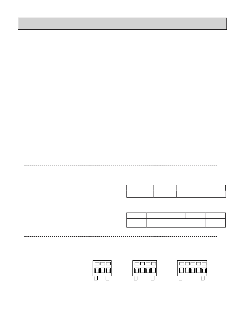
�TERMINAL� BLOCK� OPTION�
�CONNECTIONS� :� Wire� clamping� terminals�
�Wire� Strip� Length:� 0.275"� (7� mm)�
�Wire� Gage:� 24-16� AWG� copper� wire�
�1� 2� 3�
�1� 2� 3� 4�
�1� 2� 3� 4� 5�
�5�
�相关PDF资料 |
PDF描述 |
|---|---|
| 195-5MST | SWITCH SIDE ACTUATED 5 SEC |
| E-9R | SCOTCHLOK RATCHETING CRIMP TOOL |
| CUB3T300 | MODULE LCD TIMER 1 HR W/ RESET |
| 3586-12 | TOOL UNIVERSAL PISTOL GRIP |
| CUB3T320 | MODULE LCD TIMER .01 HR W/ RESET |
相关代理商/技术参数 |
参数描述 |
|---|---|
| CUB7TVSO | 制造商:Red Lion Controls 功能描述:ELECTRONIC TIMER VOLTAGE LCD 制造商:Red Lion Controls 功能描述:ELECTRONIC TIMER, VOLTAGE, LCD |
| CUB7W000 | 功能描述:COUNTER 8-DIGIT REFLECT VOLT-IN RoHS:是 类别:工业控制,仪表 >> 计数器 系列:CUB7 其它有关文件:Declaration of Conformity 标准包装:1 系列:99766 计数速率:25Hz 数字/字母数:5 输入类型:机电式脉冲 输出类型:- 电源电压:24V 显示器类型:十进制拨轮 |
| CUB7W010 | 功能描述:COUNTER 8-DIGIT YEL BKLT VOLT-IN RoHS:是 类别:工业控制,仪表 >> 计数器 系列:CUB7 其它有关文件:Declaration of Conformity 标准包装:1 系列:99766 计数速率:25Hz 数字/字母数:5 输入类型:机电式脉冲 输出类型:- 电源电压:24V 显示器类型:十进制拨轮 |
| CUB7W020 | 功能描述:COUNTER 8-DIGIT RED BKLT VOLT-IN RoHS:是 类别:工业控制,仪表 >> 计数器 系列:CUB7 其它有关文件:Declaration of Conformity 标准包装:1 系列:99766 计数速率:25Hz 数字/字母数:5 输入类型:机电式脉冲 输出类型:- 电源电压:24V 显示器类型:十进制拨轮 |
| CUB8A-1 | 制造商:IMO Precision Controls Ltd 功能描述:INVERTER 1 PHASE 1.5KW 制造商:IMO Precision Controls Ltd 功能描述:AC MOTOR DRIVER; Supply Voltage Min:200VAC; Supply Voltage Max:240VAC; No. of Phases:Single; Power Rating:1.5kW; Output Voltage Max:230V; External Depth:151mm; Frequency Range:0.1 to 400Hz; Input Current:16.4A; Output Current:8A ;RoHS Compliant: Yes |
发布紧急采购,3分钟左右您将得到回复。