- 您现在的位置:买卖IC网 > PDF目录376516 > D2525P892 Telecommunication IC PDF资料下载
参数资料
| 型号: | D2525P892 |
| 英文描述: | Telecommunication IC |
| 中文描述: | 通信集成电路 |
| 文件页数: | 3/10页 |
| 文件大小: | 261K |
| 代理商: | D2525P892 |

Data Sheet
March 2000
Wavelength-Selected D2525P
Isolated DFB Laser Module with PMF
3
Lucent Technologies Inc.
Absolute Maximum Ratings
Stresses in excess of the absolute maximum ratings can cause permanent damage to the device. These are abso-
lute stress ratings only. Functional operation of the device is not implied at these or any other conditions in excess
of those given in the operations sections of the data sheet. Exposure to absolute maximum ratings for extended
periods can adversely affect device reliability.
* Does not apply to shipping container.
Parameter
Symbol
V
RLMAX
I
FLMAX
T
T
stg
V
RPDMAX
I
FPDMAX
Min
—
—
–40
–40
—
—
Max
2
225
70
70
10
2
Unit
V
mA
°
C
°
C
V
mA
Laser Reverse Voltage
dc Forward Current
Operating Case Temperature Range
Storage Case Temperature Range*
Photodiode Reverse Voltage
Photodiode Forward Current
C
Handling Precautions
Power Sequencing
To avoid the possibility of damage to the laser module
from power supply switching transients, follow this
turn-on sequence:
1. All ground connections
2. Most negative supply
3. Most positive supply
4. All remaining connections
Reverse the order for the proper turn-off sequence.
Electrostatic Discharge
CAUTION: This device is susceptible to damage as
a result of electrostatic discharge. Take
proper precautions during both han-
dling and testing. Follow guidelines
such as JEDEC Publication No. 108-A
(Dec. 1988).
Lucent employs a human-body model (HBM) for ESD-
susceptibility testing and protection-design evaluation.
ESD voltage thresholds are dependent on the critical
parameters used to define the model. A standard HBM
(resistance = 1.5 k
, capacitance = 100 pF) is widely
used and, therefore, can be used for comparison pur-
poses. The HBM ESD threshold presented here was
obtained using these circuit parameters:
Mounting Instructions
The minimum fiber bend radius is 1.50 in.
To avoid degradation in performance, mount the mod-
ule on the board as follows:
1. Place the bottom flange of the module on a flat heat
sink at least 0.5 in. x 1.180 in. (12.7 mm x 30 mm) in
size. The surface finish of the heat sink should be
better than 32
μ
in. (0.8
μ
m), and the surface flatness
must be better than 0.001 in. (25.4
mal conductive grease is optional; however, thermal
performance can be improved by up to 5% if conduc-
tive grease is applied between the bottom flange and
the heat sink.
μ
m). Using ther-
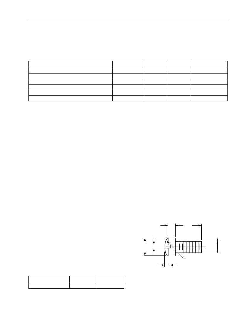
2. Mount four #2-56 screws with Fillister heads
(M2-3 mm) at the four screw hole locations (see Out-
line Diagram). The Fillister head diameter must not
exceed 0.140 in. (3.55 mm). Do not apply more than
1 in.-lb. of torque to the screws.
Note: Dimensions are in inches and (millimeters).
Figure 3. Fillister Head Screw
Parameter
Human-body Model
Value
>400
Unit
V
0.118
(3.00)
0.062 (1.58)
0.140
(3.56)
0.031 (0.79)
0.129 (3.28) R
0.086
(2.18)
0.041 (1.04)
1-532(C)
相关PDF资料 |
PDF描述 |
|---|---|
| D2525P893 | Telecommunication IC |
| D2525P894 | Telecommunication IC |
| D2525P895 | Telecommunication IC |
| D2525P896 | Telecommunication IC |
| D2525P897 | Telecommunication IC |
相关代理商/技术参数 |
参数描述 |
|---|---|
| D2525P893 | 制造商:AGERE 制造商全称:AGERE 功能描述:Telecommunication IC |
| D2525P894 | 制造商:AGERE 制造商全称:AGERE 功能描述:Telecommunication IC |
| D2525P895 | 制造商:AGERE 制造商全称:AGERE 功能描述:Telecommunication IC |
| D2525P896 | 制造商:AGERE 制造商全称:AGERE 功能描述:Telecommunication IC |
| D2525P897 | 制造商:AGERE 制造商全称:AGERE 功能描述:Telecommunication IC |
发布紧急采购,3分钟左右您将得到回复。