- 您现在的位置:买卖IC网 > PDF目录21928 > D2HW-BR271M (Omron Electronics Inc-EMC Div)SWITCH LEVER SPDT 2A SEALED PDF资料下载
参数资料
| 型号: | D2HW-BR271M |
| 厂商: | Omron Electronics Inc-EMC Div |
| 文件页数: | 8/10页 |
| 文件大小: | 0K |
| 描述: | SWITCH LEVER SPDT 2A SEALED |
| 产品培训模块: | Snap Switches |
| 产品目录绘图: | D2HW Series Post Right D2HW-SimRollerLever_16.0 |
| 标准包装: | 20 |
| 系列: | D2HW |
| 电路: | 单刀双掷 |
| 开关功能: | 开-瞬时 |
| 触点额定电压: | 2A @ 12VDC |
| 触动器类型: | 按片,仿真滚轴 |
| 安装类型: | 底座安装 |
| 端接类型: | 导线引线 |
| 操作力: | 183gf |
| 产品目录页面: | 2539 (CN2011-ZH PDF) |
| 其它名称: | D2HWBR271M SW741 |
�� �
�
�Precautions�
�Be� sure� to� read� the� precautions� and� information� common� to� all� Snap� Action� and� Detection� Switches,� contained� in� the� Technical� User’s� Guide,�
�“Snap� Action� Switches,� Technical� Information”� for� correct� use.�
�■� Cautions�
�Degree� of� Protection�
�IEC� Publication� 529,� degree� of� protection� IP67.�
�Do� not� use� this� product� in� water.� Although� molded� lead� wire� models�
�satisfy� the� test� conditions� for� the� standard� given� below,� this� test� is� to�
�check� the� ingress� of� water� into� the� switch� enclosure� after� submerging�
�the� Switch� in� water� for� a� given� time.� Satisfying� this� test� condition�
�does� not� mean� that� the� Switch� can� be� used� in� water.�
�Do� not� operate� the� Switch� when� it� is� exposed� to� water� spray,� or� when�
�water� drops� adhere� to� the� Switch� surface,� or� during� sudden� tempera-�
�ture� changes,� otherwise� water� may� intrude� into� the� interior� of� the�
�Switch� due� to� a� suction� effect.�
�Prevent� the� Switch� from� coming� into� contact� with� oil� and� chemicals.�
�Otherwise,� damage� to� or� deterioration� of� Switch� materials� may�
�result.�
�Do� not� use� the� Switch� in� areas� where� it� is� exposed� to� silicon� adhe-�
�sives,� oil,� or� grease,� otherwise� faulty� contact� may� result� due� to� the�
�generation� of� silicon� oxide.�
�Terminal� Connection�
�When� soldering� the� lead� wire� to� the� terminal,� first� insert� the� lead� wire�
�conductor� through� the� terminal� hole� and� then� conduct� soldering.�
�Made� sure� that� the� capacity� of� the� soldering� iron� is� 30� W� maximum.�
�Do� not� take� more� than� 3� s� to� solder� the� switch� terminal.� Improper� sol-�
�dering� involving� an� excessively� high� temperature� or� excessive� sol-�
�dering� time� may� deteriorate� the� characteristics� of� the� Switch.�
�When� soldering� the� lead� wire� to� the� PCB� terminal,� pay� careful� atten-�
�tion� so� that� the� flux� and� solder� liquid� level� does� not� exceed� the� PCB�
�level.�
�Side-actuated� (Cam/Dog)� Operation�
�■� Correct� Use�
�Mounting�
�Turn� OFF� the� power� supply� before� mounting� or� removing� the� Switch,�
�wiring,� or� performing� maintenance� or� inspection.� Failure� to� do� so� may�
�result� in� electric� shock� or� burning.�
�For� M3-screw� mounting� models,� use� M3� mounting� screws� with� plane�
�washers� or� spring� washers� to� securely� mount� the� Switch.� Tighten� the�
�screws� to� a� torque� of� 0.27� to� 0.29� N·m.� Exceeding� the� specified�
�torque� may� result� in� deterioration� of� the� sealing� or� damage.�
�For� models� with� posts,� secure� the� posts� by� thermal� caulking� or� by�
�pressing� into� an� attached� device.� When� pressed� into� an� attached�
�device,� provide� guides� on� the� opposite� ends� of� the� posts� to� ensure�
�that� they� do� not� fall� out� or� rattle.�
�Mount� the� Switch� onto� a� flat� surface.� Mounting� on� an� uneven� surface�
�may� cause� deformation� of� the� Switch,� resulting� in� faulty� operation� or�
�damage.�
�Operating� Body�
�Use� an� operating� body� with� low� frictional� resistance� and� of� a� shape�
�that� will� not� interfere� with� the� sealing� rubber,� otherwise� the� plunger�
�may� be� damaged� or� the� sealing� may� deteriorate.�
�Handling�
�Do� not� handle� the� Switch� in� a� way� that� may� cause� damage� to� the�
�sealing� rubber.�
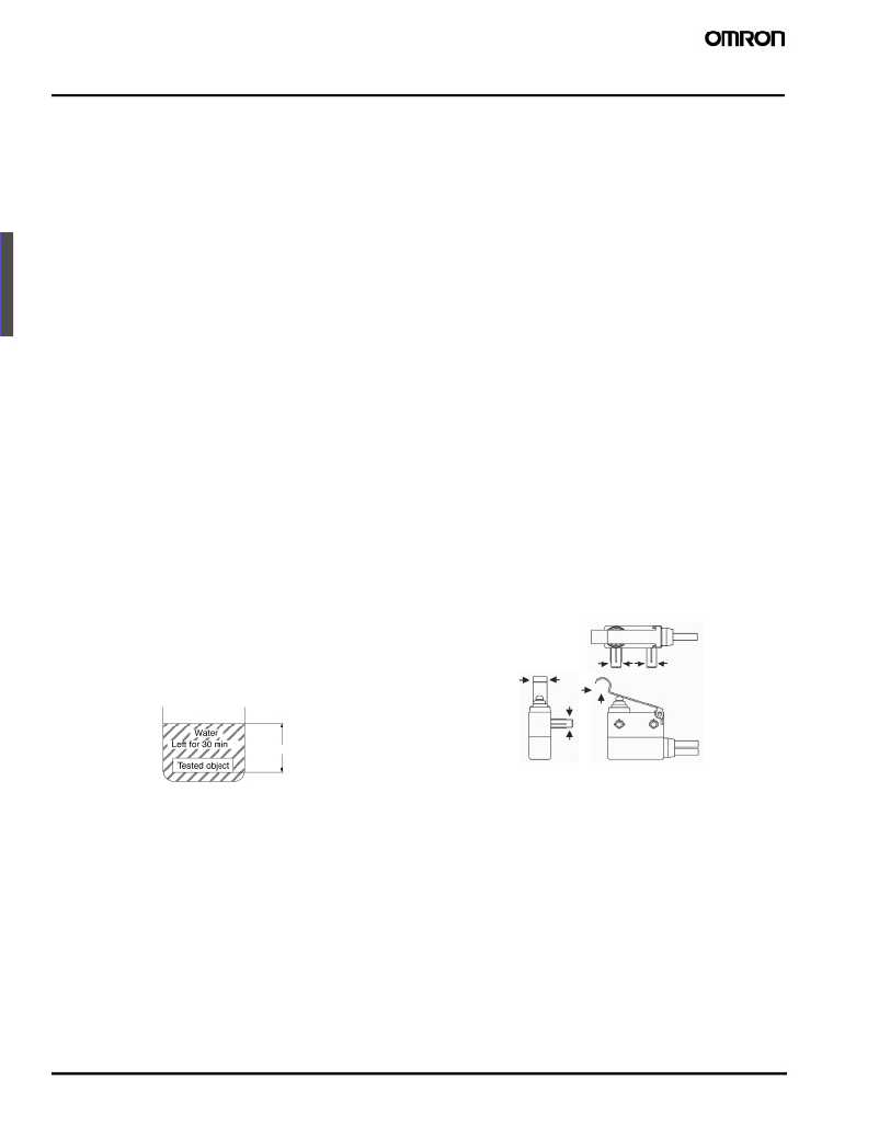
�When� handling� the� Switch,� ensure� that� pressure� is� not� applied� to� the�
�posts� in� the� directions� shown� in� the� following� diagram.� Also,� ensure�
�that� uneven� pressure� or� pressure� in� a� direction� other� than� the� operat-�
�ing� direction� is� not� applied� to� the� Actuator� as� shown� in� the� following�
�diagram.� Otherwise,� the� post,� Actuator,� or� Switch� may� be� damaged,�
�or� the� service� life� may� be� reduced.�
�When� using� a� cam� or� dog� to� operate� the� Switch,� factors� such� as� the�
�operating� speed,� operating� frequency,� push-button� indentation,� and�
�material� and� shape� of� the� cam� or� dog� will� affect� the� durability� of� the�
�Switch.� Confirm� performance� specifications� under� actual� operation�
�conditions� before� using� the� Switch� in� applications.�
�IEC� Publication� 529,� degree� of� protection� IP67.�
�Wiring� Molded� Lead� Wire� Models�
�When� wiring� molded� lead� wire� models,� ensure� that� there� is� no� weight�
�on� the� wire� or� that� there� are� no� sharp� bends� near� the� parts� where� the�
�wire� is� drawn� out.� Otherwise,� damage� to� the� Switch� or� deterioration�
�in� the� sealing� may� result.�
�Using� Micro� Loads�
�Even� when� using� micro� load� models� within� the� operating� range,�
�inrush� currents� or� surges� may� decrease� the� life� expectancy� of� the�
�Switch.� Therefore,� insert� a� contact� protection� circuit� where� neces-�
�sary.�
�188�
�Sealed� Subminiature� Snap� Action� Switch�
�D2HW�
�相关PDF资料 |
PDF描述 |
|---|---|
| AS5163-HTST | IC ENCODER ROTARY 14-TSSOP |
| D2VW-5L2A-1 | SWITCH 5A LEVER SPDT-NO SOLDER |
| D2VW-5-3MS | SWITCH 5A SPST-NO LEAD WIRE |
| ABJ363841 | SWITCH TURQ SPST LEAF SILV WIRE |
| D2FW-G083M | SWITCH LONGLEVER SPST-NO .1A SLD |
相关代理商/技术参数 |
参数描述 |
|---|---|
| D2HWBR272M | 制造商:Omron Electronic Components LLC 功能描述:SWIT SA NC SPST SIMULATED LEAF LVR WIRE LEAD 2A 42VDC 1.79N - Trays 制造商:Omron Electronic Components LLC 功能描述:SUBMINIATURE BASIC SWITCH 制造商:Omron Electronic Components LLC 功能描述:Switch Snap Action N.C. SPST Simulated Roller Leaf Lever Wire Lead 2A 125VAC 42VDC 1.8N Screw Mount |
| D2HW-BR272M | 功能描述:基本/快动开关 Subminiature Basic Switch RoHS:否 制造商:Omron Electronics 触点形式:SPDT 执行器:Lever 电流额定值:5 A 电压额定值 AC:250 V 电压额定值 DC:30 V 功率额定值: 工作力:120 g IP 等级:IP 67 NEMA 额定值: 端接类型:Wire 安装:Panel |
| D2HWBR272ML | 制造商:Omron Electronic Components LLC 功能描述:SWIT SA NC SPST SIMULATED LEAF LVR RA 2A 42VDC 1.79N TH - Trays 制造商:Omron Electronic Components LLC 功能描述:SUBMINIATURE BASIC SWITCH 制造商:Omron Electronic Components LLC 功能描述:Switch Snap Action N.C. SPST Simulated Roller Leaf Lever Wire Lead 2A 125VAC 42VDC 1.8N Screw Mount |
| D2HW-BR272ML | 功能描述:基本/快动开关 Subminiature Basic Switch RoHS:否 制造商:Omron Electronics 触点形式:SPDT 执行器:Lever 电流额定值:5 A 电压额定值 AC:250 V 电压额定值 DC:30 V 功率额定值: 工作力:120 g IP 等级:IP 67 NEMA 额定值: 端接类型:Wire 安装:Panel |
| D2HWBR272MR | 制造商:Omron Electronic Components LLC 功能描述:SWIT SA NC SPST SIMULATED LEAF LVR RA 2A 42VDC 1.79N TH - Trays 制造商:Omron Electronic Components LLC 功能描述:SUBMINIATURE BASIC SWITCH 制造商:Omron Electronic Components LLC 功能描述:Switch Snap Action N.C. SPST Simulated Roller Leaf Lever Wire Lead 2A 125VAC 42VDC 1.8N Screw Mount |
发布紧急采购,3分钟左右您将得到回复。