- 您现在的位置:买卖IC网 > PDF目录298985 > DCT104803P (TEXAS INSTRUMENTS INC) SWITCHING REGULATOR, 440 kHz SWITCHING FREQ-MAX, PDIP22 PDF资料下载
参数资料
| 型号: | DCT104803P |
| 厂商: | TEXAS INSTRUMENTS INC |
| 元件分类: | 稳压器 |
| 英文描述: | SWITCHING REGULATOR, 440 kHz SWITCHING FREQ-MAX, PDIP22 |
| 封装: | PLASTIC, DIP-28 |
| 文件页数: | 7/11页 |
| 文件大小: | 154K |
| 代理商: | DCT104803P |
DCT104803
DCT104805
SLVS407 – OCTOBER 2001
5
www.ti.com
VI
SNUB2
C7
220 pF
R2
47 R
SNUB1
RSD
3
25
4
28
1
PWMa
R5
1 k
C3
100 nF
8
2,7,26
27
PWMb
0 V(dev)
0 VI
BIAS
VO
COMP
REF
0 V(sense)
0 VO
10
19,20
11
13
12
15,16
C4
100 nF
R1
R7 470 R
R4
R3
C5
100 nF
C6
470
F
Output
Volts
V(sense)
0 V(sense)
Output 0 V
R6
0.75
C2
100 nF
C1
22
F
Input
Volts
Remote
Shutdown
Input 0 V
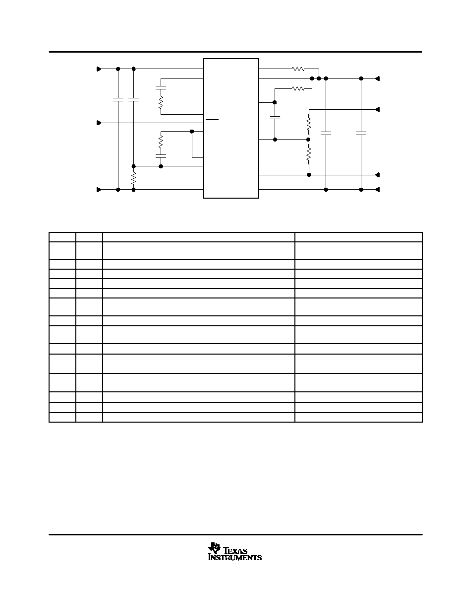
DCT1048XX
Figure 1. Schematic
schematic information
ITEM
REF
DESCRIPTION
GENERAL INFORMATION
1
C1
22
F, 100 V, ultralow impedance electrolytic capacitor. 105°C. Ripple
current at 100 kHz >80 mA.
2
C2
100 nF, 100 V, X7R dielectric
3
C3
100 nF, 25 V, X7R dielectric
4
C4
100 nF, 25 V, X7R dielectric
5
C5
100 nF, 25 V, X7R dielectric
6
C6
470
F, 10 V, ultralow impedance electrolytic capacitor. 105°C. Ripple
current at 100 kHz > 400 mA
Capacitor value should not exceed 470
F
7
C7
220 pF, 100 V, X7R, dielectric
8
R1
5%, power rating > 10 mW
R1 = 100
, DCT104803
R1 = 270
, DCT104805
9
R2
47 R, 5%, power rating
≥ 250 mW
10
R3
Power rating > 10 mW
See application section for more information
R3 = 20 k
, DCT104803
R3 = 10 k
, DCT104805
11
R4
Power rating > 10 mW
See application section for more information
R4 = 12 k
, DCT104803
R4 = 3.3 k
, DCT104805
12
R5
1 k
, 5%, power rating >10 mW
13
R6
0.75
, 5%, power rating ≥ 250 mW
14
R7
470 R, 5%, power rating > 10 mW
detailed description
The DCT10 switching topology is based on a buck derived, full-bridge converter. The output is sensed and
compared with a secondary side reference and an error signal is fed back via an optocoupler to the PWM
controller.
The converter construction is based on well developed industry standard integrated circuit processes. A copper
leadframe is used for mounting the components. The magnetic devices are glued into position and the
terminations are soldered onto the leadframe using high temperature solder. The silicon dice are mounted onto
the leadframe with silver loaded epoxy and the bond connections are ultrasonically welded onto the leadframe.
The complete assembly is transfer moulded using a silica-filled epoxy material.
PR
O
DU
C
T
PREVIEW
相关PDF资料 |
PDF描述 |
|---|---|
| DCW1033 | DC-DC REG PWR SUPPLY MODULE |
| DCW1042 | DC-DC REG PWR SUPPLY MODULE |
| DC | POLYCARBONATE, FEMALE; MALE, CIRCULAR CONNECTOR, CRIMP; SOLDER, PLUG; RECEPTACLE |
| DD105N8K | 105 A, 800 V, SILICON, RECTIFIER DIODE |
| DD175N30K-A | 223 A, 3000 V, SILICON, RECTIFIER DIODE |
相关代理商/技术参数 |
参数描述 |
|---|---|
| DCT1080 | 制造商:未知厂家 制造商全称:未知厂家 功能描述:Analog IC |
| DCT1081 | 制造商:未知厂家 制造商全称:未知厂家 功能描述:Analog IC |
| DCT10EPC-U02S002 | 功能描述:变压器音频和信号 DCT10EPC-U02S002 RoHS:否 制造商:Skyworks Solutions, Inc. 频率范围:810 MHz to 960 MHz 初级线圈阻抗: 次级线圈阻抗: 绝缘电压:23 dB 工作温度范围:- 40 C to + 85 C 端接类型:SMD/SMT 尺寸:6 mm L x 4.9 mm W x 1.6 mm H 产品:Splitters and Combiners |
| DCT-1105 | 制造商:Johnson Electric / Parlex Corporation 功能描述: |
| DCT-1105-1 | 制造商:Johnson Electric / Parlex Corporation 功能描述: |
发布紧急采购,3分钟左右您将得到回复。