- 您现在的位置:买卖IC网 > PDF目录11389 > DEA1X3A100JD1B (Murata Electronics North America)CAP CER 10PF 1KV 5% RADIAL PDF资料下载
参数资料
| 型号: | DEA1X3A100JD1B |
| 厂商: | Murata Electronics North America |
| 文件页数: | 51/84页 |
| 文件大小: | 0K |
| 描述: | CAP CER 10PF 1KV 5% RADIAL |
| 标准包装: | 3,000 |
| 系列: | DEA |
| 电容: | 10pF |
| 电压 - 额定: | 1000V(1kV) |
| 容差: | ±5% |
| 温度系数: | SL |
| 安装类型: | 通孔 |
| 工作温度: | -25°C ~ 125°C |
| 应用: | 通用 |
| 封装/外壳: | 径向 - 圆盘形 |
| 尺寸/尺寸: | 0.177" 直径(4.50mm) |
| 高度 - 座高(最大): | 0.295"(7.50mm) |
| 引线间隔: | 0.197"(5.00mm) |
| 特点: | 高电压 |
| 包装: | 散装 |
| 引线型: | 直形 |
第1页第2页第3页第4页第5页第6页第7页第8页第9页第10页第11页第12页第13页第14页第15页第16页第17页第18页第19页第20页第21页第22页第23页第24页第25页第26页第27页第28页第29页第30页第31页第32页第33页第34页第35页第36页第37页第38页第39页第40页第41页第42页第43页第44页第45页第46页第47页第48页第49页第50页当前第51页第52页第53页第54页第55页第56页第57页第58页第59页第60页第61页第62页第63页第64页第65页第66页第67页第68页第69页第70页第71页第72页第73页第74页第75页第76页第77页第78页第79页第80页第81页第82页第83页第84页
�� �
�
�!� Note� ?� Please� read� rating� and� !� CAUTION� (for� storage,� operating,� rating,� soldering,� mounting� and� handling)� in� this� catalog� to� prevent� smoking� and/or� burning,� etc.�
�?� This� catalog� has� only� typical� speci?cations.� Therefore,� please� approve� our� product� speci?cations� or� transact� the� approval� sheet� for� product� speci?cations� before� ordering.�
�C85E.pdf�
�Apr.7,2014�
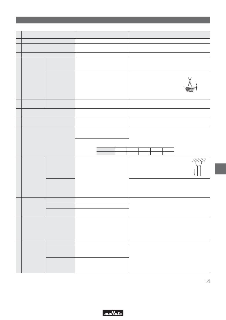
�DEB� Series� Speci?cations� and� Test� Methods�
�No.�
�1�
�2�
�3�
�Item�
�Operating� Temperature� Range�
�Appearance� and� Dimensions�
�Marking�
�Between� Lead�
�Wires�
�Specifications�
�-25� to� +85°C�
�No� visible� defect,� and� dimensions� are�
�within� specified� range.�
�To� be� easily� legible�
�No� failure�
�Test� Method�
�The� capacitor� should� be� visually� inspected� for� evidence� of�
�defect.� Dimensions� should� be� measured� with� slide� calipers.�
�The� capacitor� should� be� visually� inspected.�
�The� capacitor� should� not� be� damaged� when� DC� voltage� of�
�200%� of� the� rated� voltage� is� applied� between� the� lead� wires� for�
�1� to� 5� sec.� (Charge/Discharge� current� V� 50mA)�
�The� capacitor� is� placed� in� the� container�
�4�
�Dielectric�
�Strength�
�with� metal� balls� of� diameter� 1mm� so� that�
�each� lead� wire,� short� circuited,� is� kept�
�Body� Insulation�
�No� failure�
�about� 2mm� off� the� metal� balls� as� shown� in�
�the� figure� at� right,� and� DC� voltage� of� 1.3kV�
�is� applied� for� 1� to� 5� sec.� between� capacitor�
�About� 2mm�
�Metal� balls�
�lead� wires� and� metal� balls.�
�(Charge/Discharge� current� V� 50mA)�
�5�
�Insulation�
�Resistance� (I.R.)�
�Between� Lead�
�Wires�
�10000M� Ω� min.�
�The� insulation� resistance� should� be� measured� with�
�DC500±50V� within� 60±5� sec.� of� charging.�
�6�
�7�
�Capacitance�
�Dissipation� Factor� (D.F.)�
�Within� specified� tolerance�
�Char.� B,� E:� 2.5%� max.�
�Char.� F:� 5.0%� max.�
�Char.� B:� Within� ±10%�
�Char.� E:� Within� +20/-55%�
�The� capacitance� should� be� measured� at� 20°C� with� 1±0.2kHz�
�and� AC5V(r.m.s.)� max.�
�The� dissipation� factor� should� be� measured� at� 20°C� with�
�1±0.2kHz� and� AC5V(r.m.s.)� max.�
�The� capacitance� measurement� should� be� made� at� each� step�
�specified� in� the� Table.�
�Char.� F:� Within� +30/-80%�
�8�
�Temperature� Characteristics�
�Pre-treatment:� Capacitor� should� be� stored� at� 85±2°C� for� 1� hr.,� then� placed� at�
�room� condition*� for� 24±2� hrs.� before� measurements.�
�Step�
�Temp.� (°C)�
�1�
�20±2�
�2�
�-25±3�
�3�
�20±2�
�4�
�85±2�
�5�
�20±2�
�As� shown� in� the� figure� at� right,� fix� the� body� of�
�the� capacitor� and� apply� a� tensile� weight�
�Pull�
�gradually� to� each� lead� wire� in� the� radial�
�direction� of� the� capacitor� up� to� 10N� (5N� for�
�lead� diameter� 0.5mm),� and� keep� it� for� 10±1�
�W�
�9�
�9�
�Strength� of� Lead�
�Lead� wire� should� not� be� cut� off.�
�Capacitor� should� not� be� broken.�
�sec.�
�Each� lead� wire� should� be� subjected� to� 5N� (2.5N� for� lead�
�diameter� 0.5mm)� of� weight� and� bent� 90°� at� the� point� of� egress,�
�Bending�
�in� one� direction,� then� returned� to� its� original� position� and� bent�
�90°� in� the� opposite� direction� at� the� rate� of� one� bend� in� 2� to� 3�
�sec.�
�Appearance�
�No� marked� defect�
�The� capacitor� should� be� firmly� soldered� to� the� supporting� lead�
�10�
�Vibration�
�Resistance�
�Capacitance�
�D.F.�
�Within� specified� tolerance�
�Char.� B,� E:� 2.5%� max.�
�Char.� F:� 5.0%� max.�
�wire� and� vibrated� at� a� frequency� range� of� 10� to� 55Hz,� 1.5mm� in�
�total� amplitude,� with� about� a� 1-minute� rate� of� vibration� change�
�from� 10Hz� to� 55Hz� and� back� to� 10Hz.� Apply� for� a� total� of� 6� hrs.,�
�2� hrs.� each� in� 3� mutually� perpendicular� directions.�
�The� lead� wire� of� a� capacitor� should� be� dipped� into� a� ethanol�
�11� Solderability� of� Leads�
�Appearance�
�Lead� wire� should� be� soldered� with�
�uniform� coating� on� the� axial� direction�
�over� 3/4� of� the� circumferential� direction.�
�No� marked� defect�
�solution� of� 25wt%� rosin� and� then� into� molten� solder� for� 2±0.5�
�sec.� In� both� cases� the� depth� of� dipping� is� up� to� about� 1.5� to�
�2mm� from� the� root� of� lead� wires.�
�Temp.� of� solder:� Lead� Free� Solder� (Sn-3Ag-0.5Cu)� 245±5°C�
�H63� Eutectic� Solder� 235±5°C�
�The� lead� wire� should� be� immersed� into� the� melted� solder� of�
�12�
�Soldering� Effect�
�(Non-Preheat)�
�Capacitance�
�Change�
�Dielectric� Strength�
�(Between� Lead�
�Wires)�
�Char.� B:� Within� ±5%�
�Char.� E:� Within� ±15%�
�Char.� F:� Within� ±20%�
�Per� item� 4.�
�350±10°C� (Body� of� ?5mm� and� under:� 270±5°C)� up� to� about� 1.5�
�to� 2mm� from� the� main� body� for� 3.5±0.5� sec.�
�(Body� of� ?5mm� and� under:� 5±0.5� sec.)�
�Pre-treatment:� Capacitor� should� be� stored� at� 85±2°C� for� 1� hr.,�
�then� placed� at� room� condition*� for� 24±2� hrs.�
�before� initial� measurements.�
�Post-treatment:� Capacitor� should� be� stored� for� 4� to� 24� hrs.� at�
�room� condition.*�
�*� "Room� condition"� Temperature:� 15� to� 35°C,� Relative� humidity:� 45� to� 75%,� Atmospheric� pressure:� 86� to� 106kPa�
�Continued� on� the� following� page.�
�49�
�相关PDF资料 |
PDF描述 |
|---|---|
| VI-26Y-IY | CONVERTER MOD DC/DC 3.3V 33W |
| GRM31BR73A471KW01L | CAP CER 470PF 1KV 10% X7R 1206 |
| VI-26Y-IX | CONVERTER MOD DC/DC 3.3V 49.5W |
| VI-26Y-IW | CONVERTER MOD DC/DC 3.3V 66W |
| VI-26X-IY | CONVERTER MOD DC/DC 5.2V 50W |
相关代理商/技术参数 |
参数描述 |
|---|---|
| DEA1X3A100JP2A | 功能描述:瓷片电容器 10pF 1000volts SL 5% RoHS:否 制造商:Vishay/Cera-Mite 电容:0.01 uF 容差:20 % 电压额定值:3 kV 工作温度范围:- 25 C to + 105 C 损耗因数 DF: 端接类型:Radial 产品:High Voltage Ceramic Disc Capacitors |
| DEA1X3A101J | 制造商:MURATA 制造商全称:Murata Manufacturing Co., Ltd. 功能描述:Safety Certified Ceramic Capacitors |
| DEA1X3A101JA2B | 功能描述:瓷片电容器 100pF 1000volts SL 5% RoHS:否 制造商:Vishay/Cera-Mite 电容:0.01 uF 容差:20 % 电压额定值:3 kV 工作温度范围:- 25 C to + 105 C 损耗因数 DF: 端接类型:Radial 产品:High Voltage Ceramic Disc Capacitors |
| DEA1X3A101JB2B | 功能描述:瓷片电容器 100pF 1000 Volts 5% RoHS:否 制造商:Vishay/Cera-Mite 电容:0.01 uF 容差:20 % 电压额定值:3 kV 工作温度范围:- 25 C to + 105 C 损耗因数 DF: 端接类型:Radial 产品:High Voltage Ceramic Disc Capacitors |
| DEA1X3A101JN2A | 功能描述:瓷片电容器 100pF 1000volts SL 5% RoHS:否 制造商:Vishay/Cera-Mite 电容:0.01 uF 容差:20 % 电压额定值:3 kV 工作温度范围:- 25 C to + 105 C 损耗因数 DF: 端接类型:Radial 产品:High Voltage Ceramic Disc Capacitors |
发布紧急采购,3分钟左右您将得到回复。