- 您现在的位置:买卖IC网 > PDF目录11262 > DG406BDW-E3 (Vishay Siliconix)IC ANALOG SWITCH SPDT 28SOIC PDF资料下载
参数资料
| 型号: | DG406BDW-E3 |
| 厂商: | Vishay Siliconix |
| 文件页数: | 11/16页 |
| 文件大小: | 0K |
| 描述: | IC ANALOG SWITCH SPDT 28SOIC |
| 标准包装: | 250 |
| 功能: | 多路复用器 |
| 电路: | 1 x 16:1 |
| 导通状态电阻: | 100 欧姆 |
| 电压电源: | 单/双电源 |
| 电压 - 电源,单路/双路(±): | 12V,±15V |
| 电流 - 电源: | 30µA |
| 工作温度: | -40°C ~ 85°C |
| 安装类型: | 表面贴装 |
| 封装/外壳: | 28-SOIC(0.295",7.50mm 宽) |
| 供应商设备封装: | 28-SOIC W |
| 包装: | 管件 |
DG406B, DG407B
www.vishay.com
Vishay Siliconix
S13-2513-Rev. D, 09-Dec-13
4
Document Number: 72552
For technical questions, contact: analogswitchtechsupport@vishay.com
THIS DOCUMENT IS SUBJECT TO CHANGE WITHOUT NOTICE. THE PRODUCTS DESCRIBED HEREIN AND THIS DOCUMENT
ARE SUBJECT TO SPECIFIC DISCLAIMERS, SET FORTH AT www.vishay.com/doc?91000
Notes
a. Guaranteed by ± 15 V leakage test, not production tested.
b. Room = 25 °C, Full = as determined by the operating temperature suffix.
c. Typical values are for DESIGN AID ONLY, not guaranteed nor subject to production testing.
d. The algebraic convention whereby the most negative value is a minimum and the most positive a maximum, is used in this datasheet.
e. Guaranteed by design, not subject to production test.
f. VIN = input voltage to perform proper function.
g.
R
DS(on) = RDS(on) max. - RDS(on) min.
h. Worst case isolation occurs on channel 4 due to proximity to the drain pin.
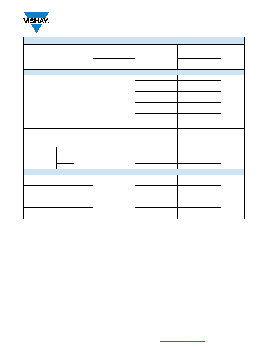
Dynamic Characteristics
Transition Time
tTRANS
see figure 2
Room
115
-
148
ns
Full
-
161
Break-Before-Make Interval
tOPEN
see figure 4
Room
39
10
-
Full
-
21
-
Enable Turn-On Time
tON(EN)
see figure 3
Room
75
-
107
Full
-
123
Enable Turn-Off Time
tOFF(EN)
Room
50
-
88
Full
-
94
Charge Injection
Q
CL = 1 nF, VS = 0 V
RS = 0
Room
11
-
pC
Off Isolationh
OIRR
VEN = 0 V, RL = 50 ,
f = 1 MHz
Room
-86
-
dB
Source Off Capacitance
CS(off)
VEN = 0 V, VS = 0 V,
f = 1 MHz
Room
6
-
pF
Drain Off
Capacitance
CD(off)
VEN = 0 V,
VD = 0 V,
f = 1 MHz
Room
108
-
DG407B
Room
54
-
Drain On
Capacitance
DG406B
CD(on)
Room
114
-
DG407B
Room
57
-
Power Supplies
Positive Supply Current
I+
VEN = VA = 0 V or 5 V
Room
23
-
30
μA
Full
-
75
Negative Supply Current
I-
Room
-0.02
-1
-
Full
-
-10
-
Positive Supply Current
I+
VEN = 2.4 V, VA = 0 V
Room
28
-
500
Full
-
700
Negative Supply Current
I-
Room
-0.01
-20
-
Full
-
-20
-
SPECIFICATIONS
PARAMETER
SYMBOL
TEST CONDITIONS
UNLESS OTHERWISE
SPECIFIED
TEMP.b
TYP.c
D SUFFIX
-40 °C to 85 °C
UNIT
V+ = 15 V, V- = -15 V
MIN.d
MAX.d
VAL = 0.8 V, VAH = 2.4 Vf
相关PDF资料 |
PDF描述 |
|---|---|
| RPER72A104K3P1C07B | CAP CER 0.1UF 100V 10% RADIAL |
| DG406BDJ-E3 | IC ANALOG SWITCH SPDT 28DIP |
| RPER72A104K3K1C07B | CAP CER 0.1UF 100V 10% RADIAL |
| DG407BDN-E3 | IC MUX CMOS ANLG DUAL 8CH 28PLCC |
| DEHR33F152KN7A | CAP CER 1500PF 3.15KV RADIAL |
相关代理商/技术参数 |
参数描述 |
|---|---|
| DG406BP | 制造商:未知厂家 制造商全称:未知厂家 功能描述:GTO Thyristors - Disc / Puk Devices |
| DG406BP12 | 制造商:Dynex Semiconductor 功能描述:GTO THYRISTOR |
| DG406BP13 | 制造商:Dynex Semiconductor 功能描述:GTO THYRISTOR |
| DG406BP18 | 制造商:Dynex Semiconductor 功能描述:GTO THYRISTOR |
| DG406BP20 | 制造商:Dynex Semiconductor 功能描述:GTO THYRISTOR |
发布紧急采购,3分钟左右您将得到回复。