- 您现在的位置:买卖IC网 > PDF目录258135 > DGP12U5S5 (POWER-ONE INC) 1-OUTPUT 12 W DC-DC REG PWR SUPPLY MODULE PDF资料下载
参数资料
| 型号: | DGP12U5S5 |
| 厂商: | POWER-ONE INC |
| 元件分类: | 电源模块 |
| 英文描述: | 1-OUTPUT 12 W DC-DC REG PWR SUPPLY MODULE |
| 封装: | ROHS COMPLIANT PACKAGE-7 |
| 文件页数: | 2/4页 |
| 文件大小: | 123K |
| 代理商: | DGP12U5S5 |
DGP12 Single-Output DC-DC Series Data Sheet
MCD10150 Rev. 1.0, 08-Mar-10
Page 2 of 4
www.power-one.com
NOTES
:
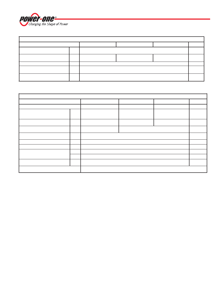
(1) All parameters measured at Tc = 25 °C, nominal input voltage and
full-rated load unless otherwise noted.
(2) Reduced output power available at 3.5 V input. Full output power
is available above 4.6 V input.
(3) Noise measurement bandwidth is 0-20 MHz for peak-to-peak
measurements; 10 kHz to 1 MHz for RMS measurements. Output
noise is measured with a 0.01 μF ceramic capacitor in parallel with a
1μF, 35V Tantalum capacitor located 1” away from the converter to
simulate your PCB’s standard decoupling. Input reflected ripple is
measured into a 10VμH source impedance.
(4) Short-term stability is specified after a 30-minute warmup at full
load, constant line, and recording the drift over a 24-hour period.
(5) No minimum load required for operation. Dynamic regulation may
degrade when run with less than 5% load.
(6) Less than 30 seconds.
s
r
e
t
e
m
a
r
a
P
t
u
p
n
I
)
1
(
l
e
d
o
M5
S
5
U
2
1
P
G
D2
1
S
5
U
2
1
P
G
D5
1
S
5
U
2
1
P
G
Ds
t
i
n
U
)
1
(
e
g
n
a
R
e
g
a
t
l
o
V
N
I
M
X
A
M
5
.
3
6
1
C
D
V
d
a
o
L
ll
u
F
t
n
e
r
u
C
t
u
p
n
I
d
a
o
L
o
N
P
Y
T
P
Y
T
0
8
2
0
1
0
5
3
6
1
0
7
4
3
0
2
A
m
y
c
n
e
u
q
e
r
F
g
n
i
h
c
t
i
w
SP
Y
T0
6z
H
k
,
e
g
a
t
l
o
v
r
e
v
O
t
u
p
n
I
m
u
m
i
x
a
M
m
u
m
i
x
a
M
s
m
0
1
X
A
M0
2C
D
V
,
e
m
i
T
n
o
-
n
r
u
T
r
o
r
E
t
u
p
t
u
O
%
1
P
Y
T0
1s
m
s
r
e
t
e
m
a
r
a
P
t
u
p
t
u
O
)
1
(
l
e
d
o
M5
S
5
U
2
1
P
G
D2
1
S
5
U
2
1
P
G
D5
1
S
5
U
2
1
P
G
Ds
t
i
n
U
e
g
a
t
l
o
V
t
u
p
t
u
O5
2
15
1C
D
V
y
c
a
r
u
c
A
e
g
a
t
l
o
V
t
u
p
t
u
O
N
I
M
P
Y
T
X
A
M
5
9
.
4
0
.
5
0
.
5
0
9
.
1
0
.
2
1
0
1
.
2
1
0
9
.
4
1
0
.
5
1
0
1
.
5
1
C
D
V
)
5
(
e
g
n
a
R
d
a
o
L
d
e
t
a
R
N
I
M
X
A
M
0
.
0
.
2
0
.
0
.
1
0
.
0
8
.
0
A
n
o
i
t
a
l
u
g
e
R
d
a
o
L
d
a
o
L
x
a
M
-
d
a
o
L
x
a
M
%
5
2
P
Y
T
X
A
M
3
.
0
7
.
0
1
.
0
5
.
0
%
n
o
i
t
a
l
u
g
e
R
e
n
i
L
C
D
V
x
a
M
-
n
i
M
=
n
i
V
P
Y
T
X
A
M
1
.
0
2
.
0
%
)
4
(
y
t
il
i
b
a
t
S
m
r
e
T
t
r
o
h
SP
Y
T5
0
.
0
<s
r
H
4
2
/
%
y
t
il
i
b
a
t
S
m
r
e
T
g
n
o
LP
Y
T1
.
0
<s
r
H
k
/
%
)
3
(
k
a
e
P
-
k
a
e
P
,
e
s
i
o
NP
Y
T0
5V
m
P
e
s
i
o
N
S
M
RP
Y
T0
1V
m
s
m
r
t
n
e
i
c
i
f
e
o
C
e
r
u
t
a
r
e
p
m
e
T
P
Y
T
X
A
M
0
5
0
5
1
/
m
p
°C
n
o
i
t
c
e
t
o
r
P
t
i
u
c
r
i
C
t
r
o
h
S
)
6
(
T
U
O
-
o
t
T
U
O
+
t
i
m
i
L
t
n
e
r
u
C
m
r
e
T
t
r
o
h
S
DGP12 SERIES APPLICATION NOTES:
External Capacitance Requirements
No external capacitance is required for operation of the
DGP12 Series. The use of input capacitors with less
than 0.5 Ohms ESR may cause peaking in the input filter
and degrade filter performance. External output
capacitance is not required for operation. However, it is
recommended that 1 μF to 10 μF of tantalum and 0.001
to 0.1 μF ceramic capacitance be selected for reduced
system noise. Additional output capacitance may be
added for increased filtering, but should not exceed
400 μF.
Negative Outputs
A negative output voltage may be obtained by
connecting the +OUT to circuit ground and connecting
-OUT as the negative output.
(Continued on page 3)
相关PDF资料 |
PDF描述 |
|---|---|
| DLV-3.3/6-1.8/7-D24TN | 2-OUTPUT 37 W DC-DC REG PWR SUPPLY MODULE |
| DRD1215-92H | 2-OUTPUT 2 W DC-DC REG PWR SUPPLY MODULE |
| DRD2812-83V | 2-OUTPUT 2 W DC-DC REG PWR SUPPLY MODULE |
| DLV-3.3/6-2.5/7-D24N | 2-OUTPUT 37 W DC-DC REG PWR SUPPLY MODULE |
| DLV-3.3/6-1.5/7-D24T | 2-OUTPUT 37 W DC-DC REG PWR SUPPLY MODULE |
相关代理商/技术参数 |
参数描述 |
|---|---|
| DGP15 | 制造商:VISHAY 制造商全称:Vishay Siliconix 功能描述:Miniature Clamper/Damper Glass Passivated Rectifier |
| DGP151 | 功能描述:D-Sub触点 CONTACT 20-24AWG RoHS:否 制造商:JAE Electronics 触点类型:Socket (Female) 触点类型2:Machined Contacts 触点材料:Copper Alloy 触点电镀:Gold 线规:24-20 端接类型:Crimp |
| DGP-15-1 | 制造商:Cinch Connectors 功能描述:Contact PIN Crimp ST Cable Mount Reel |
| DGP152 | 制造商:Cinch Connectors 功能描述:Contact PIN Crimp ST Cable Mount Reel |
| DGP-15-2 | 制造商:Cinch Connectors 功能描述: |
发布紧急采购,3分钟左右您将得到回复。