- 您现在的位置:买卖IC网 > PDF目录171207 > DLV-2.5/7-1.8/7-D24N (CD TECHNOLOGIES INC) 2-OUTPUT 30 W DC-DC REG PWR SUPPLY MODULE PDF资料下载
参数资料
| 型号: | DLV-2.5/7-1.8/7-D24N |
| 厂商: | CD TECHNOLOGIES INC |
| 元件分类: | 电源模块 |
| 英文描述: | 2-OUTPUT 30 W DC-DC REG PWR SUPPLY MODULE |
| 文件页数: | 4/6页 |
| 文件大小: | 520K |
| 代理商: | DLV-2.5/7-1.8/7-D24N |
1 3 A / 3 7 W , D U A L O U T P U T , M I X E D - V O L T A G E D C / D C C O N V E R T E R S
DLV Series
Physical
Dimensions
2" x 2" x 0.5" (50.8 x 50.8 x 12.7mm)
Case Material
Diallyl phthalate, UL94V-0 rated
Pin Material
Brass, solder coated
Weight:
TBD
Primary to Secondary Insulation Level Operational
Absolute Maximum Ratings
Input Voltage:
Continuous:
D12 Models
23 Volts
D2A Models
42 Volts
D48 Models
81 Volts
Transient (100msec): D12 Models
25 Volts
D24 Models
50 Volts
D48 Models
100 Volts
Input Reverse-Polarity Protection
Input Current must be limited. TBD
minute duration. Fusing recommended.
D12A Models
6 Amps
D24A Models
4 Amps
D48A Models
2 Amps
Output Current
Current limited. Devices can withstand
an indefinite output short circuit.
On/Off Control (Pin 4) Max. Voltages
Referenced to –Input (pin 2)
No Suffix
+VIN
"N" Suffix
+8 Volts
Sync Control (Pin 3) Max. Voltages
"S" Suffix
+5.7 Volts
Storage Temperature
–40 to +120°C
Lead Temperature (Soldering, 10 sec.)
+300°C
These are stress ratings. Exposure of devices to any of these conditions may adversely
affect long-term reliability. Proper operation under conditions other than those listed in the
Performance/Functional Specifications Table is not implied, nor recommended.
4
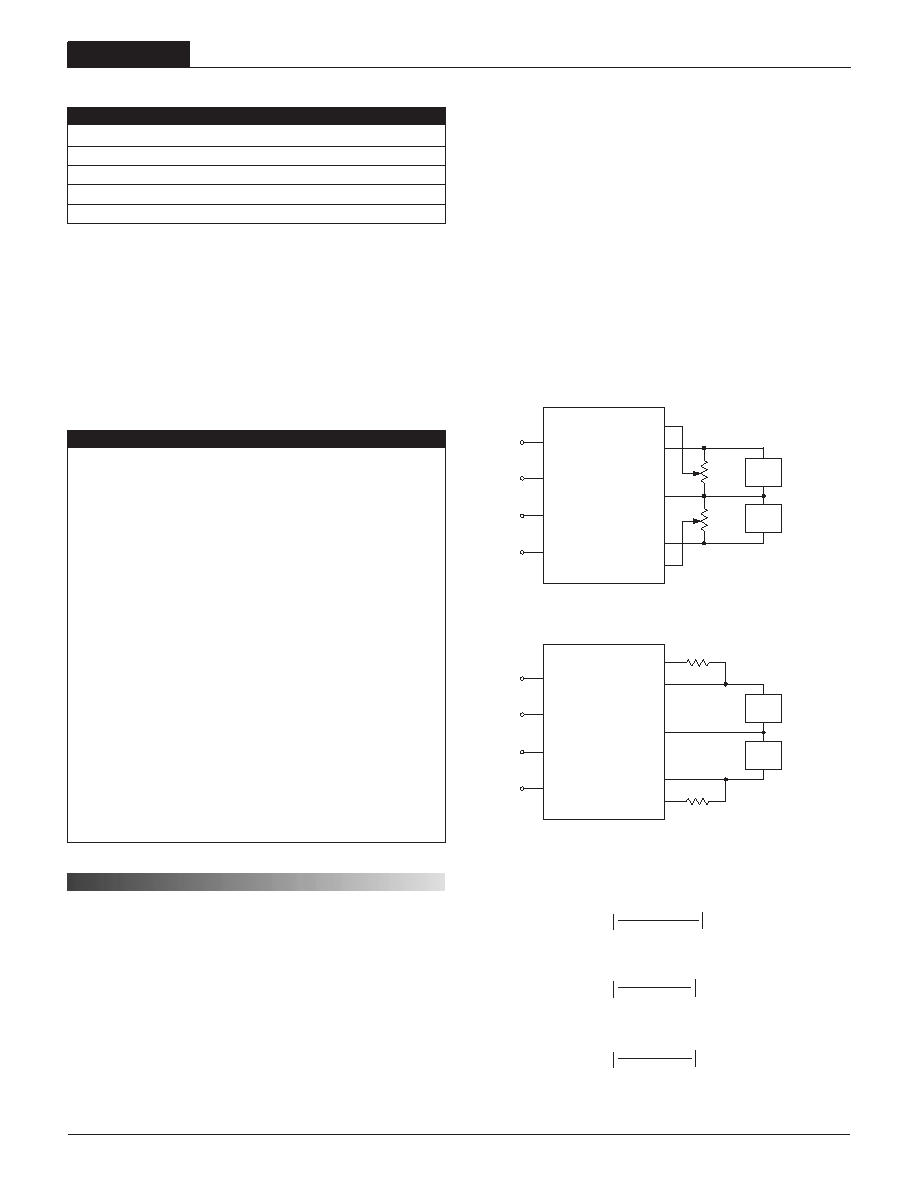
Figure 2.Trim Connections Using A Trim Pot
Figure 3.Trim Connections To Decrease Output Voltages Using Fixed Resistors
All models are specified with external TBD ceramic output capacitors.
See Technical Notes/Graphs for details.
Devices may be order with opposite polarity. See Part Number Suffixes and Technical Notes
for details.
Applying a voltage to On/Off Control (pin 4) when no input power is applied to the converter
may cause permanent damage.
Output noise may be further reduced with the installation of additional external output
capacitors. See Technical Notes.
On/Off control is designed to be driven with open collector or by appropriate voltage
levels. Voltages must be referenced to the –Input (pin 2).
Demonstrated MTBF available on request.
Trim function for the higher of two voltages available with "T" suffix. See Part Number
Suffixes and Technical Notes for details.
+3.3V
LOAD
–INPUT
ON/OFF
CONTROL
+INPUT
+3.3V OUTPUT
OUTPUT
RETURN
+2.5V OUTPUT
+2.5V TRIM
7
8
1
4
9
5
6
3
2
+2.5V
LOAD
20k
5-22
TURNS
20k
5-22
TURNS
+3.3V TRIM *
SYNC *
* OPTIONAL PIN
+3.3V
LOAD
–INPUT
ON/OFF
CONTROL
+INPUT
+3.3V OUTPUT
OUTPUT
RETURN
+2.5V OUTPUT
+2.5V TRIM
7
8
1
4
9
5
6
3
2
+2.5V
LOAD
RTRIM DOWN
+3.3V TRIM *
SYNC *
* OPTIONAL PIN
T E C H N I C A L N O T E S
Trimming Output Voltages
These DLV converters have a trim capability (pins 9 & 5) that allow users
to independently adjust the output voltages ±5%. (Note: pin 5 is an option,
see ordering information.) Adjustments to the output voltages can be accom-
plished via a trim pot, Figure 2, or a single fixed resistor as shown in Figures
3 and 4. A single fixed resistor can increase or decrease the output voltage
depending on its connection. Fixed resistors should have absolute TCR's less
than 100ppm/°C to minimize sensitivity to changes in temperature.
A single resistor connected from the Trim pin 9 to +Output (pin 8), see Figure
3, will decrease the lower output voltage. A resistor connected from Trim pin 9
to Output Return (pin 7) will increase the lower output voltage. See Figure 4.
Similarly, the higher output voltage can be adjusted using a single resistor
connected from the Trim (pin 5) to +Output (pin 6) or to Output Return (pin
7). See Figures 3 and 4.
–25.5
DOWN
RT
(k) =
3.3 – VO
3.48(VO – 1.577)
L
N
L
N
–17.4
DOWN
RT
(k) =
2.5 – VO
2.41(VO – 1.18)
L
N
L
N
2.5 Volt Trim Down
–14.17
DOWN
RT
(k) =
1.8 – VO
1.73(VO – 0.86)
L
N
L
N
1.8 Volt Trim Down
3.3 Volt Trim Down
On/Off Control
The primary-side, remote On/Off Control function (pin 4) can be specified to
operate with either positive or negative polarity. Positive polarity devices (no
suffix) are enabled when pin 4 is left open or pulled high (+TBDV to +TBDV
with respect to –Input). Positive polarity devices are disabled when pin 4 is
pulled low (0-0.8V with respect to –Input). Negative polarity devices are off
when pin 4 is high/open and on when pin 2 is pulled low.
For applications where power sequencing is critical, the DLV series can be
configured such that the On/Off Control pin will enable/disable only the higher
of the two output voltages. Contact DATEL for more information.
相关PDF资料 |
PDF描述 |
|---|---|
| DLV-2.5/7-1.8/7-D48TS | 2-OUTPUT 30 W DC-DC REG PWR SUPPLY MODULE |
| DLV-3.3/6-1.8/7-D12TN | 2-OUTPUT 37 W DC-DC REG PWR SUPPLY MODULE |
| DLV-3.3/6-1.8/7-D48TN | 2-OUTPUT 37 W DC-DC REG PWR SUPPLY MODULE |
| DLV-3.3/6-2.5/7-D48 | 2-OUTPUT 37 W DC-DC REG PWR SUPPLY MODULE |
| DLV-3.3/6-1.8/7-D12N | 2-OUTPUT 37 W DC-DC REG PWR SUPPLY MODULE |
相关代理商/技术参数 |
参数描述 |
|---|---|
| DLV-3.3 | 制造商:MURATA-PS 制造商全称:Murata Power Solutions Inc. 功能描述:Dual Output Mixed Voltage, DLV Models |
| DLV-3.3/6-1.5/7-D12 | 制造商:MURATA-PS 制造商全称:Murata Power Solutions Inc. 功能描述:Dual Output Mixed Voltage, DLV Models |
| DLV-3.3/6-1.5/7-D24 | 制造商:MURATA-PS 制造商全称:Murata Power Solutions Inc. 功能描述:Dual Output Mixed Voltage, DLV Models |
| DLV-3.3/6-1.5/7-D48 | 制造商:MURATA-PS 制造商全称:Murata Power Solutions Inc. 功能描述:Dual Output Mixed Voltage, DLV Models |
| DLV-3.3/6-1.8/7-D12 | 制造商:MURATA-PS 制造商全称:Murata Power Solutions Inc. 功能描述:Dual Output Mixed Voltage, DLV Models |
发布紧急采购,3分钟左右您将得到回复。