- 您现在的位置:买卖IC网 > PDF目录381710 > DLX1414 (Osram Opto Semiconductors GmbH) Intelligent Display Products PDF资料下载
参数资料
| 型号: | DLX1414 |
| 厂商: | Osram Opto Semiconductors GmbH |
| 英文描述: | Intelligent Display Products |
| 中文描述: | 智能显示产品 |
| 文件页数: | 1/4页 |
| 文件大小: | 196K |
| 代理商: | DLX1414 |
www.infineon.com/opto 1-888-Infineon (1-888-463-4636)
OSRAM Opto Semiconductors GmbH & Co. OHG Regensburg, Germany
www.osram-os.com +49-941-202-7178
2000 Infineon Technologies Corp. Optoelectronics Division San Jose, CA
1
May 31, 2000-12
play also provides internal memory for the four digits. With this
approach the user can asynchronously address one of four dig-
its and load new data without regard to the LED multiplex tim-
ing.
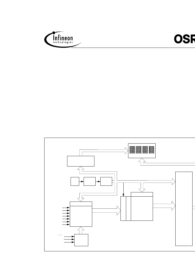
Figure 1 is a block diagram of the DLX1414. The device con-
sists of four (5x7) LED arrays and a single CMOS integrated
chip. The IC chip contains the column drivers and row drivers,
128 character ROM, four word x7 bit Random Access Memory,
oscillator for multiplexing, multiplex counter/decoder, cursor
memory, address decoder, and miscellaneous control logic.
This application note is intended to serve as a design and appli-
cation guide for users of the DLX1414 alphanumeric Intelligent
Display. The information presented covers device electrical
description and operation, considerations for general circuit
design, and interfacing the DLX1414 to microprocessors.
Electrical & Mechanical Description
The internal electronics of the Intelligent Display eliminates all
the traditional difficulties of using multi-digit light emitting dis-
plays (decoding, drivers and multiplexing). The Intelligent Dis-
Applying the DLX1414
Intelligent Display
Appnote 15
Products
Figure 1. Block Diagram–DLX1414
Rows 0 to 6
Display
Columns 0 to 19
Display
Output
Logic
Row Control Logic
& Row Drivers
Row Decoder
ROM
128x35 Bit
ASCII
Character
Decode
4480 Bits
D6
D5
D4
D3
D2
D1
D0
C
Write
Address
Decoder
RAM
Memory
Timing and Control Logic
L
4x7 Bit
OSC
÷
128
Counter
÷
7
Counter
7 Bit ASCII Code
RAM Read Logic
Column Data
WR
A0
A1
3 2 1 0
相关PDF资料 |
PDF描述 |
|---|---|
| DLX2416 | Intelligent Display Device |
| DLX3416 | Intelligent Display Device |
| DLX713X | 5x7 Dot Matrix Intelligent Display |
| DME1737 | NTC Thermistor |
| DME1737-NR | SUPER I/O WITH TEMPERATURE |
相关代理商/技术参数 |
参数描述 |
|---|---|
| DL-X1H | 制造商:Stellar Labs Power 功能描述:Dell Latitude Replacement Laptop Battery |
| DLX2000 | 制造商:未知厂家 制造商全称:未知厂家 功能描述:FIBER OPTIC TRANSCEIVER |
| DL-X200H | 制造商:Stellar labs (MCM Electronics) 功能描述:Dell Latitude Replacement Laptop Battery |
| DL-X200L | 制造商:Stellar Labs Power 功能描述:Dell Latitude Replacement Laptop Battery |
| DLX2040 | 制造商:未知厂家 制造商全称:未知厂家 功能描述:FIBER OPTIC TRANSCEIVER |
发布紧急采购,3分钟左右您将得到回复。