- 您现在的位置:买卖IC网 > PDF目录15535 > DM164134 (Microchip Technology)KIT DEV PIC18F4XK22 PDF资料下载
参数资料
| 型号: | DM164134 |
| 厂商: | Microchip Technology |
| 文件页数: | 26/116页 |
| 文件大小: | 0K |
| 描述: | KIT DEV PIC18F4XK22 |
| 标准包装: | 1 |
| 系列: | PIC® 18F |
| 类型: | MCU |
| 适用于相关产品: | PIC18F4XK22,PIC18F2XK22 |
| 所含物品: | 板,文档 |
第1页第2页第3页第4页第5页第6页第7页第8页第9页第10页第11页第12页第13页第14页第15页第16页第17页第18页第19页第20页第21页第22页第23页第24页第25页当前第26页第27页第28页第29页第30页第31页第32页第33页第34页第35页第36页第37页第38页第39页第40页第41页第42页第43页第44页第45页第46页第47页第48页第49页第50页第51页第52页第53页第54页第55页第56页第57页第58页第59页第60页第61页第62页第63页第64页第65页第66页第67页第68页第69页第70页第71页第72页第73页第74页第75页第76页第77页第78页第79页第80页第81页第82页第83页第84页第85页第86页第87页第88页第89页第90页第91页第92页第93页第94页第95页第96页第97页第98页第99页第100页第101页第102页第103页第104页第105页第106页第107页第108页第109页第110页第111页第112页第113页第114页第115页第116页
2006 Microchip Technology Inc.
DS41159E-page 23
PIC18FXX8
2.7
Effects of Sleep Mode on the
On-Chip Oscillator
When the device executes a SLEEP instruction, the
on-chip clocks and oscillator are turned off and the
device is held at the beginning of an instruction cycle
(Q1 state). With the oscillator off, the OSC1 and OSC2
signals will stop oscillating. Since all the transistor
switching currents have been removed, Sleep mode
achieves the lowest current consumption of the device
(only leakage currents). Enabling any on-chip feature
that will operate during Sleep will increase the current
consumed during Sleep. The user can wake from
Sleep through external Reset, Watchdog Timer Reset
or through an interrupt.
2.8
Power-up Delays
Power-up delays are controlled by two timers so that no
external Reset circuitry is required for most applica-
tions. The delays ensure that the device is kept in
Reset until the device power supply and clock are
stable. For additional information on Reset operation,
see Section 3.0 “Reset”.
The first timer is the Power-up Timer (PWRT), which
optionally provides a fixed delay of TPWRT (parameter
#D033) on power-up only (POR and BOR). The second
timer is the Oscillator Start-up Timer (OST), intended to
keep the chip in Reset until the crystal oscillator is
stable.
With the PLL enabled (HS4 Oscillator mode), the time-
out sequence following a Power-on Reset is different
from other oscillator modes. The time-out sequence is
as follows: the PWRT time-out is invoked after a POR
time delay has expired, then the Oscillator Start-up
Timer (OST) is invoked. However, this is still not a
sufficient amount of time to allow the PLL to lock at high
frequencies. The PWRT timer is used to provide an
additional fixed 2 ms (nominal) to allow the PLL ample
time to lock to the incoming clock frequency.
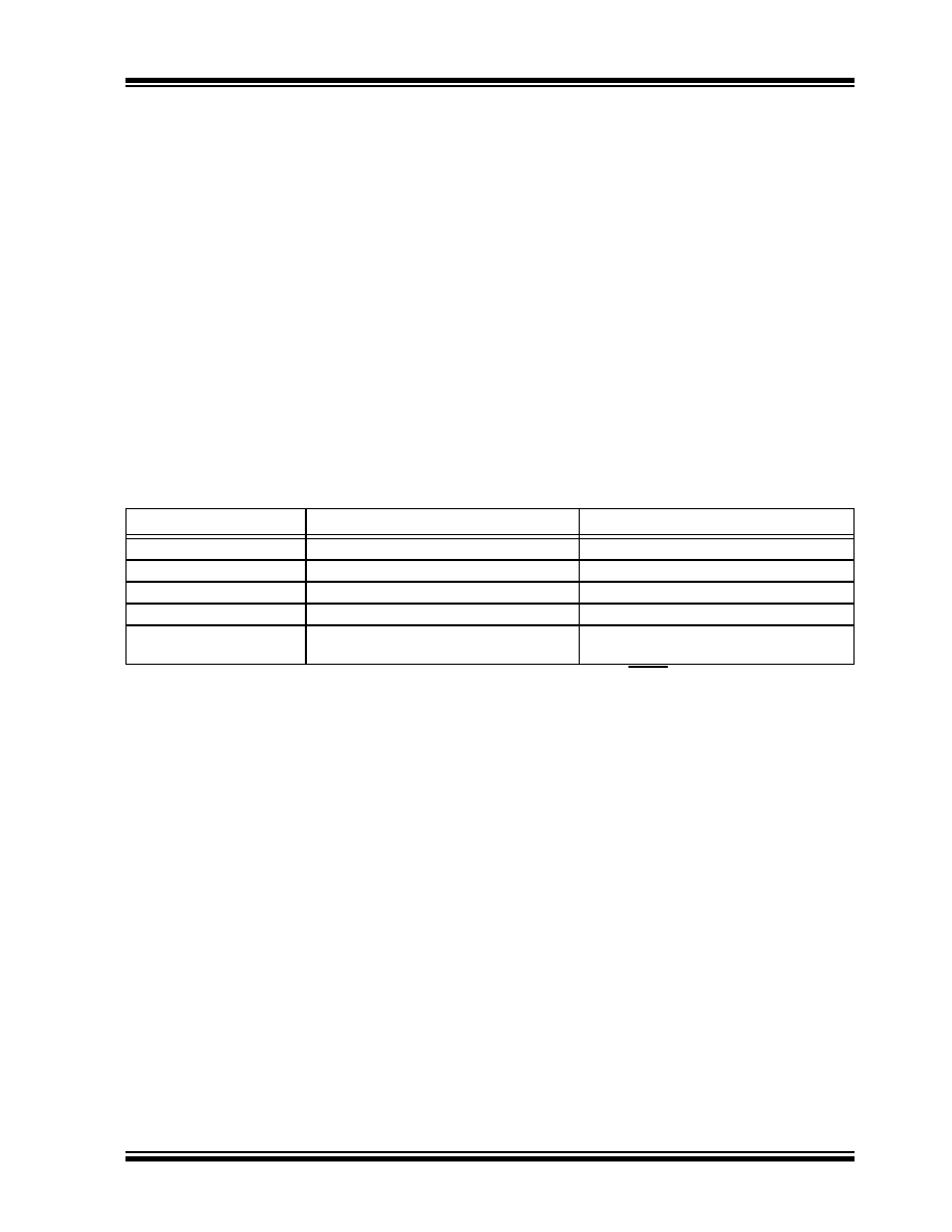
TABLE 2-3:
OSC1 AND OSC2 PIN STATES IN SLEEP MODE
OSC Mode
OSC1 Pin
OSC2 Pin
RC
Floating, external resistor should pull high
At logic low
RCIO
Floating, external resistor should pull high
Configured as PORTA, bit 6
ECIO
Floating
Configured as PORTA, bit 6
EC
Floating
At logic low
LP, XT and HS
Feedback inverter disabled at quiescent
voltage level
Feedback inverter disabled at quiescent
voltage level
Note:
See Table 3-1 in Section 3.0 “Reset” for time-outs due to Sleep and MCLR Reset.
相关PDF资料 |
PDF描述 |
|---|---|
| AIUR-07-221K | INDUCTOR POWER 220UH 10% T/H |
| MAX8903CETI+ | IC DC/DC CHARGER LI+ 2A 28-TQFN |
| MAX11080GUU/V+T | IC LI/BATTERY MANAGEMENT 38TSSOP |
| MAX11081GUU+T | IC FAULT MON BATT 12CH 38-TSSOP |
| MAX11081GUU/V+T | IC FAULT MON BATT 12CH 38TSSOP |
相关代理商/技术参数 |
参数描述 |
|---|---|
| DM164135 | 制造商:Microchip Technology Inc 功能描述:KIT, ONEPIC DEMO BOARD, PLUS PICKIT 3 制造商:Microchip Technology Inc 功能描述:KIT, ONEPIC DEMO BOARD, PLUS PICKIT 3; SVHC:No SVHC (19-Dec-2012) ;RoHS Compliant: Yes 制造商:Microchip Technology Inc 功能描述:One PIC MCU Platform Board with PICkit 3 |
| DM164135 | 制造商:Microchip Technology Inc 功能描述:PICKIT 3 IN-CIRCUIT DEBUGGER |
| DM173001 | 功能描述:开发板和工具包 - PIC / DSPIC PICDEM 17 PIC17CXX RoHS:否 制造商:Microchip Technology 产品:Starter Kits 工具用于评估:chipKIT 核心:Uno32 接口类型: 工作电源电压: |
| DM180021 | 功能描述:开发板和工具包 - PIC / DSPIC PIC18 Starter Kit RoHS:否 制造商:Microchip Technology 产品:Starter Kits 工具用于评估:chipKIT 核心:Uno32 接口类型: 工作电源电压: |
| DM1800-434MB | 功能描述:射频模块 DM1800 Base Station 433.92 MHz RoHS:否 制造商:Linx Technologies 产品:Transceiver Modules 频带:902 MHz to 928 MHz 输出功率:- 15.5 dBm to + 12.5 dBm 接口类型:UART 工作电源电压:- 0.3 VDC to + 5.5 VDC 传输供电电流:38.1 mA 接收供电电流:22.7 mA 天线连接器类型:U.FL 最大工作温度:+ 85 C 尺寸:1.15 mm x 0.63 mm x 0.131 mm |
发布紧急采购,3分钟左右您将得到回复。