- 您现在的位置:买卖IC网 > PDF目录43025 > DPKA (ITT CANNON) FEMALE; MALE, MULTIWAY RACK AND PANEL CONN, CRIMP, PLUG; RECEPTACLE PDF资料下载
参数资料
| 型号: | DPKA |
| 厂商: | ITT CANNON |
| 元件分类: | 多脚机架和面板连接器 |
| 英文描述: | FEMALE; MALE, MULTIWAY RACK AND PANEL CONN, CRIMP, PLUG; RECEPTACLE |
| 文件页数: | 7/16页 |
| 文件大小: | 494K |
| 代理商: | DPKA |
www.ittcannon.com
90
Dimensions are shown in inches (millimeters).
Dimensions subject to change.
MIL-C-83733
DPK
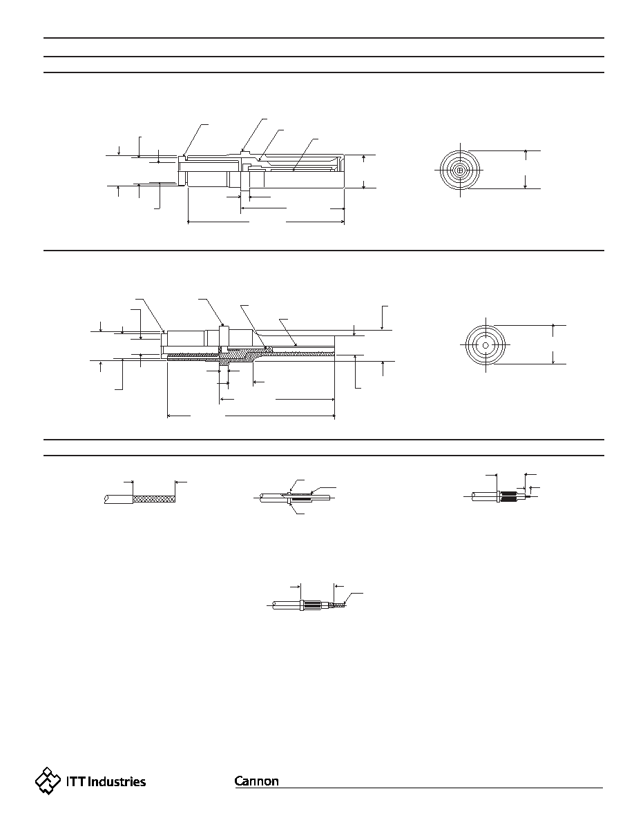
Assembly/Shielded Contacts
Assembly Instructions
Socket
249-1826-000/MIL-C-39029/51
Size 12/RG-179B/U Cable (used in 71C15 layout
249-1826-000/MIL-C-39029/50
Size 12/RG-179B/U Cable (used in 71C15 layout
FERRULE
.084 MIN. DIA.
(2.13)
BODY
INSULATOR
INNER SKT CONTACT
INNER PIN CONTACT
FERRULE
.403 REF.
(10.24)
INNER
CONTACT
Strip outer jacket to dimensions shown to expose outer conductor.
Slip (or install) ferrule over outer conductor against cable jacket.
Exposed portion of the outer conductor must be combed out then
folded back over ferrule.
Trim cable to dimensions, as shown. (Ferrule must butt against
cable jacket).
Insert cable,ferrule and inner contact to rear of shell and crimp
into place with M22520/5-03 crimp tool.
Install inner contact against dielectric then crimp contact and center
conductor with a M22520/2-01 cimp tool using a M22520/2-30
locator.
DIELECTRIC
OUTER CONDUCTOR SHALL
NOT EXCEED THIS EDGE
.122 MIN. DIA.
(3.10)
.122 MIN. DIA.
(3.10)
Pin
Step 1.
Step 2.
Step 3.
Step 5.
Step 4.
.148
± .002 DIA.
(3.75
± 0.05)
.148
± .002 DIA.
(3.75
± 0.05)
.046
± .002
(1.16
± 0.05)
.510
± .010
(12.95
± 0.25)
.118
± .003
(3.00
± 0.08)
.094
± .001
(2.38
± 0.02)
.340
± .010
(8.64
± 0.25)
.070
± .010
(1.78
± 0.25)
.151 MAX. DIA.
(3.84)
.616
± .005
(15.64
± 0.13)
.880 MAX.
(22.35)
.046
± .002
(1.16
± 0.50)
.495
± .005
(12.57
± 0.13)
.160
± .001
(4.06
± 0.02)
.187
± .002 DIA.
(4.74
± 0.05)
.187
± .002 DIA.
(4.74
± 0.05)
.756 MAX.
(19.20)
.084
± .MIN. DIA.
(2.13)
相关PDF资料 |
PDF描述 |
|---|---|
| DPKA-G131PY-7 | 131 CONTACT(S), MALE, MULTIWAY RACK AND PANEL CONN, CRIMP, RECEPTACLE |
| DPKA-G131SM | 131 CONTACT(S), FEMALE, MULTIWAY RACK AND PANEL CONN, CRIMP, PLUG |
| DPKB-101PX-7 | 101 CONTACT(S), MALE, MULTIWAY RACK AND PANEL CONN, CRIMP, RECEPTACLE |
| DT06-3S | RECTANGULAR CONNECTOR, PLUG |
| DX-P-HA26-A1-1310 | 26 CONTACT(S), MALE, TELECOM AND DATACOM CONNECTOR, IDC, PLUG |
相关代理商/技术参数 |
参数描述 |
|---|---|
| DPKA G131PK-7 | 制造商:ITT Interconnect Solutions 功能描述:Rack & Panel |
| DPKA-18PC-7 | 制造商:ITT Interconnect Solutions 功能描述:Conn Rack and Panel PIN 18 POS Crimp ST Panel Mount |
发布紧急采购,3分钟左右您将得到回复。