- 您现在的位置:买卖IC网 > PDF目录299000 > DPM2 (Electronic Theatre Controls, Inc.) 3 1/2 Digit Subminiature LCD Module PDF资料下载
参数资料
| 型号: | DPM2 |
| 厂商: | Electronic Theatre Controls, Inc. |
| 英文描述: | 3 1/2 Digit Subminiature LCD Module |
| 中文描述: | 3 1 / 2位微型液晶显示模块 |
| 文件页数: | 2/2页 |
| 文件大小: | 53K |
| 代理商: | DPM2 |
Specifications liable to change without prior warning
DPM 2
Issue 5
August/1997
M.C.
Applies to DPM 2/1
PIN FUNCTIONS
ON BOARD LINKS
SAFETY
1. V-
DPM2- negativepower supplyconnection.
DPM2S- C2negativeconnection.
2. INLO
Negativemeasuringinput. Analogueinputs must benocloser than1Vtoeither thepositiveor negativesupply.
3. INHI
Positivemeasuringinput.
Thenegativesupplyof theDPM2S is generatedinternallyandmirrors thepositivesupplyvoltage.
4. COM
Groundfor analoguesectionof A/Dconverter, it isactivelyheldat 2.8VbelowV+andmust not beallowedtosinkexcessivecurrent
(>100 A) by, for instance, connectingtoahigher voltage.
5. REFLO Negativeinput for referencevoltage.
6. REFHI Positiveinput for referencevoltage(connectedviaLinkREFtointernal reference).
7. CAP-
8. CAP+
9. GND
DPM2- noconnection.
DPM2S - 0Vpower supplyconnection.
10. V+
Positivepower supplyconnection.
Onboardlinks canbemadewithasolder linktoimplement features.
DP1 MaketoturnonDP1(199.9).
DP2 MaketoturnonDP2(19.99).
DP3 MaketoturnonDP3(1.999).
REF Factorymade- Connects internal referencetoREFHI. It shouldonlybecut if anexternal referenceisused.
To comply with the Low Voltage Directive (LVD 93/68/EEC), input voltages to the module’s pins must not exceed 60Vdc. If voltages to the
measuring inputs do exceed 60Vdc, then fit scaling resistors externally to the module. The user must ensure that the incorporation of the DPM
into the user’s equipment conforms to the relevant sections of BS EN 61010 (Safety Requirements for Electrical Equipment for Measuring,
Control andLaboratoryUse).
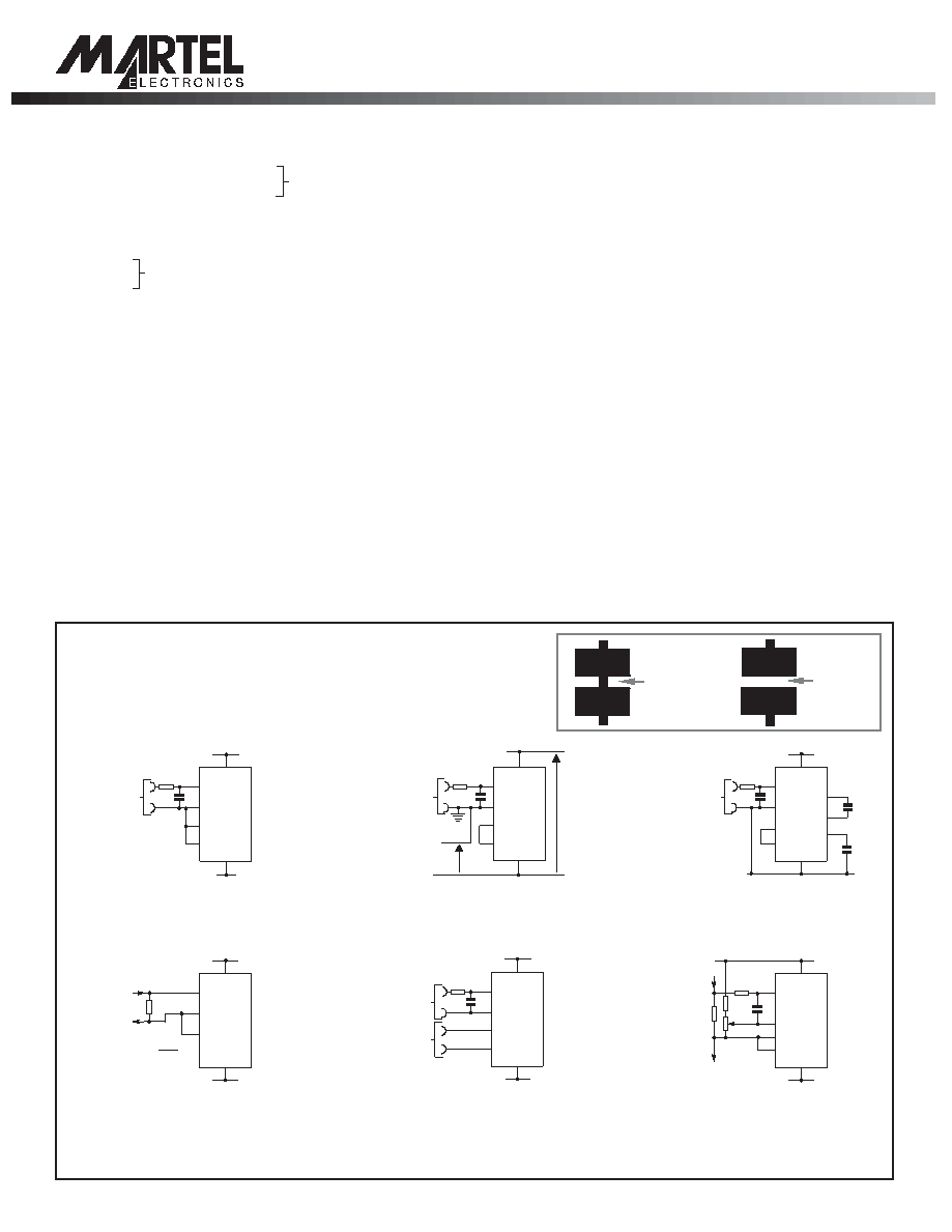
VARIOUS OPERATING MODES
ON-BOARD LINKS: In order to quickly and easily change operating modes for
different applications the meter has several "on-board links". They are designed
to be easily opened (cut) or shorted (soldered).
Do not connect more than one meter to the same power supply if the meters cannot
use the same signal ground. Input filter should be as close as possible to the meter.
Taking any input beyond the power supply rails will damage the meter.
Normally
SHORTED
Cut to
OPEN
Normally
OPEN
Solder to
SHORT
Measuring a floating voltage source
of 200mV full scale (DPM 2).
Measuring 4-20mA to read 0-999.
Supply MUST be isolated. (DPM 2)
Measuring a single ended input
referenced to supply (DPM 2S).
Split supply operation (DPM 2).
Measuring the ratio of two voltages.
Reading = 1000 V /V
50mV< V <200mV
V <2V . (DPM 2)
12
2
12
Measuring current. Supply MUST
be isolated. (DPM 2)
Charge pump capacitor connections (DPM 2S only).
V+
V-
V+
10
4
2
5
3 IN HI
IN LO
REF LO
COM
1
V-
+
-
±200mV
Check Link REF is SHORTED.
10nF
1M
V+
10
2
4
5
3 IN HI
IN LO
COM
REF LO
1 V-
V-
Check Link REF is SHORTED.
10nF
220k
5k
6R2
1M
Iin
Iout
V+
10
3
R
4
5
IN HI
REF LO
IN LO
1 V-
V-
R= 0.2
IFSR
V+
10
6
2
5
3 IN HI
IN LO
REF LO
REF HI
1
V-
+
-
+
V1
V2
Check Link REF is OPEN.
Check Link REF is SHORTED.
10nF
1M
V+ +5V
V+
10
4
2
5
3 IN HI
IN LO
REF LO
COM
CAP+
CAP-
9
V- 1
8
7
+
-
C2
1.5 F
C1
1.5 F
0V
GND
+
-
±200mV
Check Link REF is SHORTED.
10nF
1M
V+
10
4
2
5
3 IN HI
IN LO
14V max.
7V min.
1V
min.
REF LO
COM
1
V-
+
-
±200mV
Check Link REF is SHORTED.
10nF
1M
0V
P.O. Box 897, Windham, NH 03087
(603) 893-0886
(800) 821-0023
FAX (603) 898-6820
相关PDF资料 |
PDF描述 |
|---|---|
| DPS10307AK | THUMB/PUSHWHEEL SWITCH-1SWITCHES, HEXADECIMAL COMPLEMENT, 0.02A, 20VDC, PANEL MOUNT |
| DPS8137AK | THUMB/PUSHWHEEL SWITCH-1SWITCHES, BCD COMPLEMENT, 0.02A, 20VDC, PANEL MOUNT |
| DPS9SG905 | THUMB/PUSHWHEEL SWITCH-1SWITCHES, BINARY CODED DECIMAL, 0.02A, 20VDC, PANEL MOUNT |
| DPX161990DT-8003B1 | 1850 MHz(Tx), 892 MHz(Rx), DUPLEXER |
| DPX165850DT-8117A1 | 5375 MHz(Tx), 2450 MHz(Rx), DUPLEXER |
相关代理商/技术参数 |
参数描述 |
|---|---|
| DP-M2 | 制造商:PANASONIC ELECTRIC WORKS - ACSD 功能描述:SENSOR PRESSURE 2KPA DIFF 制造商:PANASONIC INDUSTRIAL AUTOMATION SALES 功能描述:SENSOR PRESSURE 2KPA DIFF |
| DPM2000 | 功能描述:METER DPM LCD3.5DIGIT 200MV IN RoHS:是 类别:工业控制,仪表 >> 仪表 - 面板,数字 系列:Legacy 标准包装:12 系列:* 其它名称:Q7072030 |
| DPM2000-2 | 功能描述:METER DPM LCD 3.5DIGIT 2V IN RoHS:是 类别:工业控制,仪表 >> 仪表 - 面板,数字 系列:Legacy 标准包装:12 系列:* 其它名称:Q7072030 |
| DPM2000-20 | 功能描述:METER DPM LCD 3.5DIGIT 20V IN RoHS:是 类别:工业控制,仪表 >> 仪表 - 面板,数字 系列:Legacy 标准包装:12 系列:* 其它名称:Q7072030 |
| DPM2000S | 功能描述:LCD DPM 5V/200MV 3.5 DIG S-RAIL RoHS:否 类别:工业控制,仪表 >> 仪表 - 面板,数字 系列:Legacy 标准包装:12 系列:* 其它名称:Q7072030 |
发布紧急采购,3分钟左右您将得到回复。