- 您现在的位置:买卖IC网 > PDF目录171220 > DQ62412QKA02PKS (SYNQOR INC) 2-OUTPUT 20 W DC-DC REG PWR SUPPLY MODULE PDF资料下载
参数资料
| 型号: | DQ62412QKA02PKS |
| 厂商: | SYNQOR INC |
| 元件分类: | 电源模块 |
| 英文描述: | 2-OUTPUT 20 W DC-DC REG PWR SUPPLY MODULE |
| 文件页数: | 6/15页 |
| 文件大小: | 617K |
| 代理商: | DQ62412QKA02PKS |
Product # DQ62412QKA02
Phone 1-888-567-9596
Doc.# 005-2DQ245L Rev. A
06/08/05
Page 14
T
Technical S
echnical Specification
pecification
Input:
Outputs:
Current:
PPackage:
ackage:
35-75V
2.45V & 1.225V
20W
Quarter-brick
Input Filtering and External Capacitance: Figure E pro-
vides a diagram showing the internal input filter components.
This filter dramatically reduces input terminal ripple current,
which otherwise could exceed the rating of an external elec-
trolytic input capacitor.
The recommended external input
capacitance is specified in the “Input Characteristics” section.
More detailed information is available in the application note
titled “EMI Characteristics” on the SynQor website.
Startup Inhibit Period: The Startup Inhibit Period ensures
that the converter will remain off for at least 200ms when it is
shut down for any reason. When an output short is present,
this generates a 5Hz "hiccup mode," which prevents the con-
verter from overheating. In all, there are seven ways that the
converter can be shut down, initiating a Startup Inhibit Period:
Input Under-Voltage Lockout
Input Over-Voltage Shutdown (not present in Quarter-brick)
Output Over-Voltage Protection
Over Temperature Shutdown
Current Limit
Short Circuit Protection
Turned off by the ON/OFF input
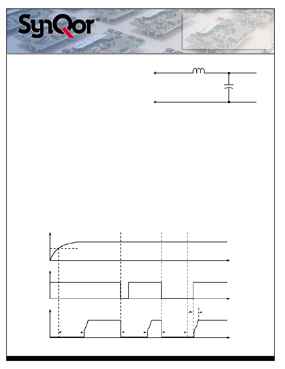
Figure F shows three turn-on scenarios, where a Startup Inhibit
Period is initiated at t0, t1, and t2:
Before time t0, when the input voltage is below the UVL thresh-
old, the unit is disabled by the Input Under-Voltage Lockout fea-
ture. When the input voltage rises above the UVL threshold, the
Input Under-Voltage Lockout is released, and a Startup Inhibit
Period is initiated. At the end of this delay, the ON/OFF pin is
evaluated, and since it is active, the unit turns on.
At time t1, the unit is disabled by the ON/OFF pin, and it can-
not be enabled again until the Startup Inhibit Period has
elapsed.
When the ON/OFF pin goes high after t2, the Startup Inhibit
Period has elapsed, and the output turns on within the typical
Turn-On Time.
L
C
Vin(+)
Vin(_)
Figure E: Internal Input Filter Diagram (values listed on page 3).
Under-Voltage
Lockout Turn-On
Threshold
ON/OFF
(pos logic)
Figure F: Startup Inhibit Period (turn-on time not to scale)
Vout
Vin
200ms
TBDms
(typical start-up
inhibit period)
t0
t1
t2
t
4ms (typical
turn on time)
ON
OFF
相关PDF资料 |
PDF描述 |
|---|---|
| DQ62412QKA02NKS | 2-OUTPUT 20 W DC-DC REG PWR SUPPLY MODULE |
| DQ63325QGL09PNT | 2-OUTPUT 87 W DC-DC REG PWR SUPPLY MODULE |
| DR1040-100-R | 1 ELEMENT, 10 uH, FERRITE-CORE, GENERAL PURPOSE INDUCTOR, SMD |
| DR1040-5R2-R | 1 ELEMENT, 5.2 uH, FERRITE-CORE, GENERAL PURPOSE INDUCTOR, SMD |
| DR124-101-R | 1 ELEMENT, 100 uH, FERRITE-CORE, GENERAL PURPOSE INDUCTOR, SMD |
相关代理商/技术参数 |
参数描述 |
|---|---|
| DQ62412QKA02PNS | 制造商:SYNQOR 制造商全称:SYNQOR 功能描述:Quarter-brick DC/DC Converter |
| DQ62412QKA02PRS | 制造商:SYNQOR 制造商全称:SYNQOR 功能描述:Quarter-brick DC/DC Converter |
| DQ62412QKA02PYS | 制造商:SYNQOR 制造商全称:SYNQOR 功能描述:Quarter-brick DC/DC Converter |
| DQ63312QGL07 | 制造商:SYNQOR 制造商全称:SYNQOR 功能描述:Dual Output, High Efficiency, Isolated DC/DC Converter |
| DQ63312QGL07NKS | 制造商:SYNQOR 制造商全称:SYNQOR 功能描述:Dual Output, High Efficiency, Isolated DC/DC Converter |
发布紧急采购,3分钟左右您将得到回复。