- 您现在的位置:买卖IC网 > PDF目录223666 > DRC-11522-294L (DATA DEVICE CORP) DIGITAL TO SYNCHRO OR RESOLVER, MDMA36 PDF资料下载
参数资料
| 型号: | DRC-11522-294L |
| 厂商: | DATA DEVICE CORP |
| 元件分类: | 位置变换器 |
| 英文描述: | DIGITAL TO SYNCHRO OR RESOLVER, MDMA36 |
| 封装: | DOUBLE WIDTH, KOVAR, DIP-36 |
| 文件页数: | 4/8页 |
| 文件大小: | 111K |
| 代理商: | DRC-11522-294L |
4
Data Device Corporation
www.ddc-web.com
DRC-11522
Rev. J
TECHNICAL INFORMATION
DIGITAL INPUTS
For each channel, the 16-bit digital angle is double buffered with
transparent latches (See FIGURE 1). The latch controls have
internal pull-up current sources to +5 V, this puts the latches in
the transparent mode when they are not connected.
The angle is determined by adding the logic bits. The enable
inputs are LL (1st Latch LSBs), LM (1st Latch MSBs), and LA
(2nd Latch All); see FIGURE 2 for timing.
OUTPUT SCALING AND REFERENCE LEVEL
ADJUSTMENT
The DRC-11522 operates like a multiplying D/A converter in that
the voltage of each output line is directly proportional to the ref-
erence voltage. The maximum line-to-line levels are determined
by the output amplifiers and are programmable for a gain of 0.5,
1.0, or 2.0 (See TABLE 2.).
OUTPUT PHASING AND OUTPUT SCALE FACTOR
The analog output signals have the following phasing:
sin = (REF * K) Ao [1 + A(θ)] sin θ
cos = (REF * K) Ao [1 + A(θ)] cos θ
The output amplifiers simultaneously track reference voltage
fluctuations because they are proportional to (REF * K). The
transformation ratio Ao is determined by the programmable gain
inputs (0.5, 1.0, or 2.0). The maximum variation in Ao from all
causes is 0.1%. The term A(
θ) represents the variation of the
amplitude with the digital signal input angle. A(
θ), which is called
the scale factor variation, is a smooth function of (
θ) without dis-
continuities and is less than ±0.1% for all values of (
θ). The total
maximum variation in Ao[1 + A(θ)] is therefore ±0.2%.
Because the amplitude factor (REF * K) Ao [1 + A(θ)] varies
simultaneously on all output lines, it is not a source of error when
the DRC-11522 is driving a ratiometric system. However, if the
outputs are used independently, as in x-y plotters, the amplitude
variations must be taken into account.
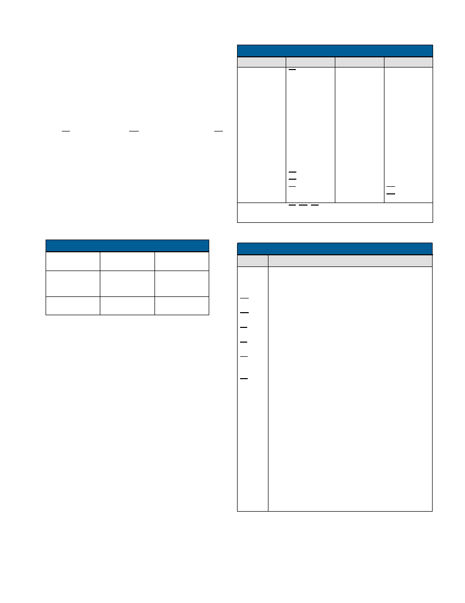
TABLE 2. PROGRAMMABLE GAIN
GC1-A
(PIN 7)
GC2-A
(PIN 8)
GAIN
(K)
GND
OPEN
GND
OPEN
0.5
1.0
2.0
GC1-B
(PIN 4)
GC2-B
(PIN 5)
GAIN
(K)
TABLE 3. PINOUTS
PIN
FUNCTION
PIN
FUNCTION
1
2
3
4
5
6
7
8
9
10
11
12
13
14
15
16
17
18
LL-B
COS A
SIN A
GC1-B
GC2-B
Ref B
GC1-A
GC2-A
Ref A
COS B
SIN B
NC
+15 V
-15 V
LA-B
LA-A
LL-A
GND
19
20
21
22
23
24
25
26
27
28
29
30
31
32
33
34
35
36
Bit 16 (LSB)
Bit 15
Bit 14
Bit 13
Bit 12
Bit 11
Bit 10
Bit 9
Bit 8
Bit 7
Bit 6
Bit 5
Bit 4
Bit 3
Bit 2
Bit 1 (MSB)
LM-A
LM-B
NOTE: Functions LL, LM, LA both A and B may be left unconnected
when not used.
TABLE 4. PIN DEFINITIONS
PIN
DEFINITION
GND
B1-B16
LM-A
LM-B
LL-A
LL-B
LA-A
LA-B
+15 V
-15 V
Ref-A
Ref-B
GC1-A
GC2-A
GC1-B
GC2-B
Sin A
Cos A
Sin B
Cos B
Power Supply Ground
Digital Ground
Analog Signal Ground
Digital Input bits, B1 = MSB = 180 degrees
High Byte Enable (B1-B8) for MSB’s 8-bit Input register of
channel A. Logic high enables, low holds.
High Byte Enable (B1-B8) for MSB’s 8-bit Input register
channel B Logic high enables, low holds.
Low Byte Enable (B9-B16) for LSB’s 8-bit Input register of
channel A. Logic high enables, low holds
Low Byte Enable (B9-B16) for LSB’s 8-bit Input register of
channel B. Logic high enables, low holds.
Channel A Load Converter. Logic high transfers Channel A
input registers data into 16-bit holding register. When
low, Channel A is in hold mode.
Channel B Load Converter. Logic high transfers Channel B
input registers data into 16-bit holding register. When
low, Channel B is in hold mode.
Power Supply Voltage.
CAUTION:
REVERSAL OF POWER SUPPLIES
WILL DAMAGE THE CONVERTER.
Channel A reference voltage input
Channel B reference voltage input
Channel A gain programming pin
Channel B gain programming pin
Analog output of Channel A
Analog output of Channel B
相关PDF资料 |
PDF描述 |
|---|---|
| DRC-11522-334Z | DIGITAL TO SYNCHRO OR RESOLVER, MDMA36 |
| DRC-11522-103Q | DIGITAL TO SYNCHRO OR RESOLVER, MDMA36 |
| DRC-11522-434W | DIGITAL TO SYNCHRO OR RESOLVER, MDMA36 |
| DRC-11522-804Y | DIGITAL TO SYNCHRO OR RESOLVER, MDMA36 |
| DRC-11522-844Y | DIGITAL TO SYNCHRO OR RESOLVER, MDMA36 |
相关代理商/技术参数 |
参数描述 |
|---|---|
| DRC12-24PA | 制造商:TE Connectivity / Deutsch 功能描述: |
| DRC12-40PA | 制造商:TE Connectivity / Deutsch 功能描述: |
| DR-C-12V | 制造商:Panasonic Electric Works 功能描述: |
| DRC-12V100W1AZ | 功能描述:AC/DC CONVERTER 12V 72W 制造商:delta electronics 系列:Chrome 零件状态:在售 类型:封闭式 输出数:1 电压 - 输入:90 ~ 264 VAC 电压 - 输出 1:12V 电压 - 输出 2:- 电压 - 输出 3:- 电压 - 输出 4:- 电流 - 输出(最大值):6A 功率(W):72W 应用:ITE(商业) 电压 - 隔离:3kV 效率:86% 工作温度:-25°C ~ 71°C(有降额) 特性:可调输出,DC 输入能力,通用输入 安装类型:DIN 轨道 大小/尺寸:3.58" 长 x 3.54" 宽 x 2.19" 高(90.9mm x 89.9mm x 55.6mm) 所需最小负载:- 认可:CB,CE,cULus,cURus,TUV 标准包装:40 |
| DRC-12V10W1AZ | 功能描述:AC/DC CONVERTER 12V 10W 制造商:delta electronics 系列:Chrome 零件状态:有效 类型:封闭式 输出数:1 电压 - 输入:90 ~ 264 VAC 电压 - 输出 1:12V 电压 - 输出 2:- 电压 - 输出 3:- 电压 - 输出 4:- 电流 - 输出(最大值):830mA 功率(W):10W 应用:ITE(商业) 电压 - 隔离:3kV(3000V) 效率:82% 工作温度:-25°C ~ 71°C(有降额) 特性:DC 输入能力,IP20,通用输入 安装类型:DIN 轨道 大小/尺寸:2.19" 长 x 0.71" 宽 x 3.58" 高(55.6mm x 18.0mm x 91.0mm) 所需最小负载:- 认可:CB,CE,cULus,cURus,TUV 功率(W) - 最大值:10W 标准包装:24 |
发布紧急采购,3分钟左右您将得到回复。