- 您现在的位置:买卖IC网 > PDF目录97859 > DS1305E (MAXIM INTEGRATED PRODUCTS INC) 0 TIMER(S), REAL TIME CLOCK, PDSO20 PDF资料下载
参数资料
| 型号: | DS1305E |
| 厂商: | MAXIM INTEGRATED PRODUCTS INC |
| 元件分类: | Timer or RTC |
| 英文描述: | 0 TIMER(S), REAL TIME CLOCK, PDSO20 |
| 封装: | 0.173 INCH, TSSOP-20 |
| 文件页数: | 21/22页 |
| 文件大小: | 309K |
| 代理商: | DS1305E |
DS1305
8 of 22
AIE1 (Alarm Interrupt Enable 1) – When set to a logic 1, this bit permits the interrupt 1 request flag
(IRQF1) bit in the status register to assert INT1 (when INTCN = 1) or to assert INT0 (when INTCN = 0).
When the AIE1 bit is set to logic 0, the IRQF1 bit does not initiate an interrupt signal.
STATUS REGISTER (READ 10h)
BIT7
BIT6
BIT5
BIT4
BIT3
BIT2
BIT1
BIT0
0
IRQF1
IRQF0
IRQF0 (Interrupt 0 Request Flag) – A logic 1 in the interrupt request flag bit indicates that the current
time has matched the Alarm 0 registers. If the AIE0 bit is also a logic 1, the INT0 pin goes low. IRQF0 is
cleared when the address pointer goes to any of the Alarm 0 registers during a read or write.
IRQF1 (Interrupt 1 Request Flag) – A logic 1 in the interrupt request flag bit indicates that the current
time has matched the Alarm 1 registers. This flag can be used to generate an interrupt on either INT0 or
INT1
depending on the status of the INTCN bit in the control register. If the INTCN bit is set to a logic 1
and IRQF1 is at a logic 1 (and AIE1 bit is also a logic 1), the INT1 pin goes low. If the INTCN bit is set
to a logic 0 and IRQF1 is at a logic 1 (and AIE1 bit is also a logic 1), the INT0 pin goes low. IRQF1 is
cleared when the address pointer goes to any of the Alarm 1 registers during a read or write.
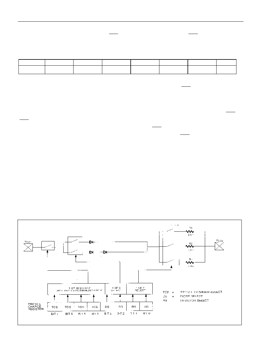
TRICKLE CHARGE REGISTER (READ 11H, WRITE 91H)
This register controls the trickle charge characteristics of the DS1305. The simplified schematic of Figure
3 shows the basic components of the trickle charger. The trickle-charge select (TCS) bits (bits 4–7)
control the selection of the trickle charger. To prevent accidental enabling, only a pattern of 1010 enables
the trickle charger. All other patterns disable the trickle charger. On the initial application of power, the
DS1305 powers up with the trickle charger disabled. The diode select (DS) bits (bits 2–3) select whether
one diode or two diodes are connected between VCC1 and VCC2. The resistor select (RS) bits select the
resistor that is connected between VCC1 and VCC2. The resistor and diodes are selected by the RS and DS
bits, as shown in Table 3.
Figure 3. PROGRAMMABLE TRICKLE CHARGER
相关PDF资料 |
PDF描述 |
|---|---|
| DS1306N | 0 TIMER(S), REAL TIME CLOCK, PDIP16 |
| DS1306 | 0 TIMER(S), REAL TIME CLOCK, PDIP16 |
| DS1306E | 0 TIMER(S), REAL TIME CLOCK, PDSO20 |
| DS1306EN | 0 TIMER(S), REAL TIME CLOCK, PDSO20 |
| DS1307Z | 1 TIMER(S), REAL TIME CLOCK, PDSO8 |
相关代理商/技术参数 |
参数描述 |
|---|---|
| DS1305E/R | 制造商:DALLAS 制造商全称:Dallas Semiconductor 功能描述:Serial Alarm Real-Time Clock |
| DS1305E/T | 制造商:DALLAS 制造商全称:Dallas Semiconductor 功能描述:Serial Alarm Real-Time Clock |
| DS1305E/T&R | 制造商:Maxim Integrated Products 功能描述:IC RTC SERIAL ALARM 20-TSSOP |
| DS1305E/T&R | 功能描述:实时时钟 RoHS:否 制造商:Microchip Technology 功能:Clock, Calendar. Alarm RTC 总线接口:I2C 日期格式:DW:DM:M:Y 时间格式:HH:MM:SS RTC 存储容量:64 B 电源电压-最大:5.5 V 电源电压-最小:1.8 V 最大工作温度:+ 85 C 最小工作温度: 安装风格:Through Hole 封装 / 箱体:PDIP-8 封装:Tube |
| DS1305E/TR | 制造商:MAXIM 制造商全称:Maxim Integrated Products 功能描述:Serial Alarm Real-Time Clock |
发布紧急采购,3分钟左右您将得到回复。