- 您现在的位置:买卖IC网 > PDF目录9406 > DS1340C-33# (Maxim Integrated Products)IC RTC I2C W/CHARGER 16-SOIC PDF资料下载
参数资料
| 型号: | DS1340C-33# |
| 厂商: | Maxim Integrated Products |
| 文件页数: | 2/16页 |
| 文件大小: | 0K |
| 描述: | IC RTC I2C W/CHARGER 16-SOIC |
| 产品培训模块: | Lead (SnPb) Finish for COTS Obsolescence Mitigation Program |
| 标准包装: | 45 |
| 类型: | 时钟/日历 |
| 特点: | 闰年,方波输出,涓流充电器 |
| 时间格式: | HH:MM:SS(24 小时) |
| 数据格式: | YY-MM-DD-dd |
| 接口: | I²C,2 线串口 |
| 电源电压: | 2.97 V ~ 5.5 V |
| 电压 - 电源,电池: | 1.3 V ~ 5.5 V |
| 工作温度: | -40°C ~ 85°C |
| 安装类型: | 表面贴装 |
| 封装/外壳: | 16-SOIC(0.295",7.50mm 宽) |
| 供应商设备封装: | 16-SOIC W |
| 包装: | 管件 |
| 产品目录页面: | 1433 (CN2011-ZH PDF) |
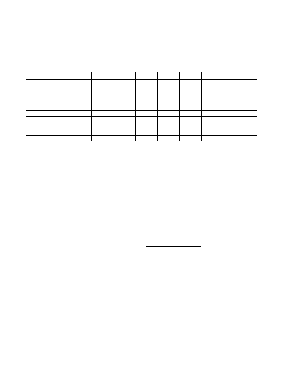
pattern on 1010 enables the trickle charger. All other
patterns disable the trickle charger. The trickle charger
is disabled when power is first applied. The diode-
select (DS) bits (bits 2, 3) select whether or not a diode
is connected between VCC and VBACKUP. If DS is 01,
no diode is selected; if DS is 10, a diode is selected.
The ROUT bits (bits 0, 1) select the value of the resistor
connected between VCC and VBACKUP. Table 3 shows
the resistor selected by the resistor select (ROUT) bits
and the diode selected by the diode select (DS) bits.
Warning: The ROUT value of 250
Ω must not be select-
ed whenever VCC is greater than 3.63V.
The user determines diode and resistor selection
according to the maximum current desired for battery
or super cap charging (Table 4). The maximum charg-
ing current can be calculated as illustrated in the fol-
lowing example.
Assume that a 3.3V system power supply is applied to
VCC and a super cap is connected to VBACKUP. Also
assume that the trickle charger has been enabled with
a diode and resistor R2 between VCC and VBACKUP.
The maximum current IMAX would therefore be calculat-
ed as follows:
IMAX = (3.3V - diode drop) / R2
≈ (3.3V - 0.7V) /
2k
Ω≈ 1.3mA
As the super cap charges, the voltage drop between
VCC and VBACKUP decreases and therefore the charge
current decreases.
Flag Register (09h)
Bit 7: Oscillator Stop Flag (OSF). A logic 1 in this bit
indicates that the oscillator has stopped or was
stopped for some time period and may be used to
judge the validity of the clock and calendar data. This
bit is edge triggered and is set to logic 1 when the
internal circuitry senses that the oscillator has transi-
tioned from a normal run state to a STOP condition. The
following are examples of conditions that can cause the
OSF bit to be set:
1)
The first time power is applied.
2)
The voltages present on VCC and VBACKUP
are insufficient to support oscillation.
3)
The EOSC bit is set to 1, disabling the
oscillator.
4)
External influences on the crystal (e.g., noise,
leakage).
The OSF bit remains at logic 1 until written to logic 0. It
can only be written to logic 0. Attempting to write OSF
to logic 1 leaves the value unchanged.
Bits 6 to 0: All other bits in the flag register read as 0
and cannot be written.
Clock Calibration
The DS1340 provides a digital clock calibration feature
to allow compensation for crystal and temperature vari-
ations. The calibration circuit adds or subtracts counts
from the oscillator divider chain at the divide-by-256
stage. The number of pulses blanked (subtracted for
negative calibration) or inserted (added for positive cal-
ibration) depends upon the value loaded into the five
calibration bits (CAL4–CAL0) located in the control reg-
ister. Adding counts speeds the clock up and subtract-
ing counts slows the clock down.
The calibration bits can be set to any value between 0
and 31 in binary form. Bit 5 of the control register, S, is
the sign bit. A value of 1 for the S bit indicates positive
calibration, while a value of 0 represents negative cali-
bration. Calibration occurs within a 64-minute cycle.
The first 62 minutes in the cycle can, once per minute,
I2C RTC with Trickle Charger
10
Maxim Integrated
DS1340
TCS3
TCS2
TCS1
TCS0
DS1
DS0
ROUT1
ROUT0
FUNCTION
X
0
X
Disabled
X
1
X
Disabled
X
XX
XXX0
0
Disabled
1
0
1
0
1
0
1
No diode, 250
Ω resistor
1
0
1
0
1
0
1
One diode, 250
Ω resistor
1
0
1
0
1
0
No diode, 2k
Ω resistor
1
0
1
0
1
0
1
0
One diode, 2k
Ω resistor
1
0
1
0
1
No diode, 4k
Ω resistor
1
0
1
0
1
0
1
One diode, 4k
Ω resistor
0
Power-on reset value
Table 4. Trickle-Charge Register
相关PDF资料 |
PDF描述 |
|---|---|
| DS1306+ | IC RTC SERIAL ALARM 16-DIP |
| MS27468E21B35PB | CONN RCPT 79POS JAM NUT W/PINS |
| DS1305+ | IC RTC SERIAL ALARM 16-DIP |
| DS1306E+ | IC RTC SERIAL ALARM 20-TSSOP |
| MS3121F14-18PY | CONN RCPT 18POS CBL MNT W/PINS |
相关代理商/技术参数 |
参数描述 |
|---|---|
| DS1340C-33# | 功能描述:实时时钟 I2C RTC w/Trickle Charger RoHS:否 制造商:Microchip Technology 功能:Clock, Calendar. Alarm RTC 总线接口:I2C 日期格式:DW:DM:M:Y 时间格式:HH:MM:SS RTC 存储容量:64 B 电源电压-最大:5.5 V 电源电压-最小:1.8 V 最大工作温度:+ 85 C 最小工作温度: 安装风格:Through Hole 封装 / 箱体:PDIP-8 封装:Tube |
| DS1340C-33#T&R | 制造商:Maxim Integrated Products 功能描述:I2C RTC WITH TRICKLE CHARGER 制造商:Maxim Integrated Products 功能描述:SERIAL RTC 3.3V W/CRYSTAL ROHS T/R - Tape and Reel 制造商:Maxim Integrated Products 功能描述:IC RTC I2C W/CHARGER 16-SOIC 制造商:Maxim Integrated Products 功能描述:Real Time Clock I2C RTC w/Trickle Charger |
| DS1340C-33#T&R | 功能描述:实时时钟 I2C RTC w/Trickle Charger RoHS:否 制造商:Microchip Technology 功能:Clock, Calendar. Alarm RTC 总线接口:I2C 日期格式:DW:DM:M:Y 时间格式:HH:MM:SS RTC 存储容量:64 B 电源电压-最大:5.5 V 电源电压-最小:1.8 V 最大工作温度:+ 85 C 最小工作温度: 安装风格:Through Hole 封装 / 箱体:PDIP-8 封装:Tube |
| DS1340C-33+ | 制造商:MAXIM 制造商全称:Maxim Integrated Products 功能描述:I2C RTC with Trickle Charger |
| DS1340U-18 | 功能描述:实时时钟 I2C RTC w/Trickle Charger RoHS:否 制造商:Microchip Technology 功能:Clock, Calendar. Alarm RTC 总线接口:I2C 日期格式:DW:DM:M:Y 时间格式:HH:MM:SS RTC 存储容量:64 B 电源电压-最大:5.5 V 电源电压-最小:1.8 V 最大工作温度:+ 85 C 最小工作温度: 安装风格:Through Hole 封装 / 箱体:PDIP-8 封装:Tube |
发布紧急采购,3分钟左右您将得到回复。