- 您现在的位置:买卖IC网 > PDF目录9365 > DS1374C-3#T&R (Maxim Integrated Products)IC RTC I2C 32BIT 3.0V 16-SOIC PDF资料下载
参数资料
| 型号: | DS1374C-3#T&R |
| 厂商: | Maxim Integrated Products |
| 文件页数: | 5/18页 |
| 文件大小: | 0K |
| 描述: | IC RTC I2C 32BIT 3.0V 16-SOIC |
| 产品培训模块: | Lead (SnPb) Finish for COTS Obsolescence Mitigation Program |
| 标准包装: | 1,000 |
| 类型: | 二进制计数器 |
| 特点: | 警报器,方波输出,涓流充电器,监视计时器 |
| 时间格式: | 二进制 |
| 数据格式: | 二进制 |
| 接口: | I²C,2 线串口 |
| 电源电压: | 2.7 V ~ 3.3 V |
| 电压 - 电源,电池: | 1.3 V ~ 3.7 V |
| 工作温度: | -40°C ~ 85°C |
| 安装类型: | 表面贴装 |
| 封装/外壳: | 16-SOIC(0.295",7.50mm 宽) |
| 供应商设备封装: | 16-SOIC W |
| 包装: | 带卷 (TR) |
DS1374
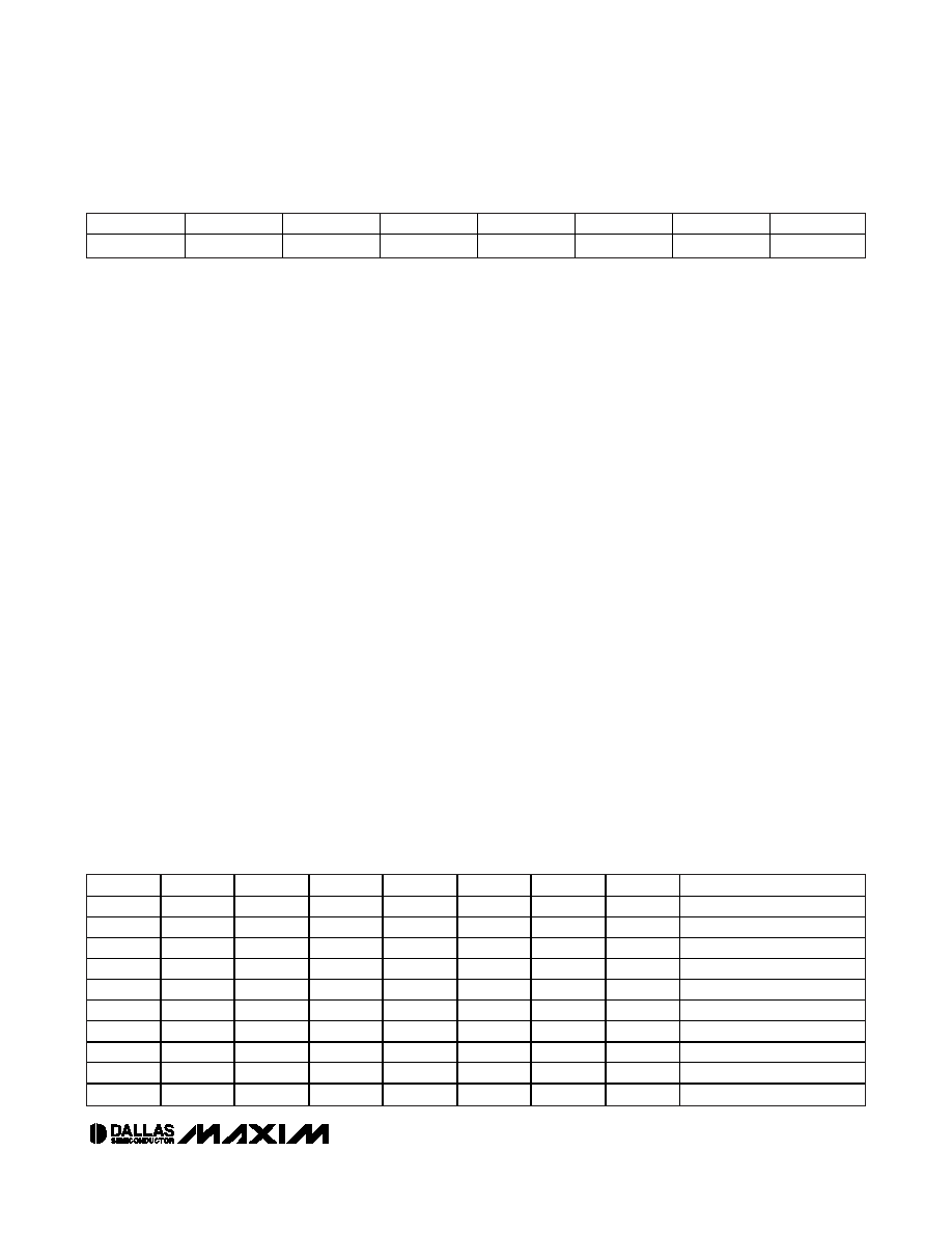
Status Register (08h)
Bit 7/Oscillator Stop Flag (OSF). A logic 1 in this bit
indicates that the oscillator either is stopped or was
stopped for some period of time and can be used to
judge the validity of the timekeeping data. This bit is set
to logic 1 any time the oscillator stops. The following
are examples of conditions that can cause the OSF bit
to be set:
1) The first time power is applied.
2) The voltage present on both VCC and VBACKUP are
insufficient to support oscillation.
3) The EOSC bit is turned off.
4) External influences on the crystal (i.e., noise, leak-
age, etc.).
This bit remains at logic 1 until written to logic 0.
Bit 0/Alarm Flag (AF). A logic 1 in the alarm flag bit
indicates that the WD/ALM counter reached zero. If
WD/ALM is set to zero and the AIE bit = 1, the INT pin
goes low and stays low until AF is cleared. AF is
cleared when written to logic 0. This bit can only be
written to logic 0. Attempting to write logic 1 leaves the
value unchanged. If WD/ALM is set to 1 and the AIE
bit = 1, the INT pin pulses low for 250ms when the
WD/ALM counter reaches zero and sets AF = 1. At the
pulse completion, the DS1374 clears the AF bit to zero.
If the 250ms pulse is active, writing AF to zero does not
truncate the pulse.
Trickle-Charge Register (10h)
The simplified schematic in Figure 7 shows the basic
components of the trickle charger. The trickle-charge
select (TCS) bits (bits 4–7) control the selection of the
trickle charger. To prevent accidental enabling, only a
pattern of 1010 enables the trickle charger. All other
patterns disable the trickle charger. The trickle charger
is disabled when power is first applied. The diode
select (DS) bits (bits 2, 3) select whether or not a diode
is connected between VCC and VBACKUP. If DS is 01,
no diode is selected; if DS is 10, a diode is selected.
The ROUT bits (bits 0, 1) select the value of the resistor
connected between VCC and VBACKUP. Table 5 shows
the resistor selected by the resistor select (ROUT) bits
and the diode selected by the diode select (DS) bits.
Warning: The ROUT value of 250
Ω must not be select-
ed whenever VCC is greater than 3.63V.
The user determines diode and resistor selection
according to the maximum current desired for battery or
super cap charging. The maximum charging current can
be calculated as illustrated in the following example.
Assume that a system power supply of 3.3V is applied
to VCC and a super cap is connected to VBACKUP. Also
assume the trickle charger has been enabled with a
diode and resistor R2 between VCC and VBACKUP. The
maximum current IMAX would therefore be calculated
as follows:
IMAX = (3.3V - diode drop) / R2
≈ (3.3V - 0.7V) / 2kΩ ≈
1.3mA
As the super cap changes, the voltage drop between
VCC and VBACKUP decreases and therefore the charge
current decreases.
Bit 7
Bit 6
Bit 5
Bit 4
Bit 3
Bit 2
Bit 1
Bit 0
OSF
00
AF
I2C, 32-Bit Binary Counter Watchdog RTC with
Trickle Charger and Reset Input/Output
____________________________________________________________________
13
TCS3
TCS2
TCS1
TCS0
DS1
DS0
ROUT1
ROUT0
FUNCTION
X
0
X
Disabled
X
1
X
Disabled
X
XXX0
0
Disabled
1
0
1
0
1
0
1
No diode, 250
Ω resistor
1
0
1
0
1
0
1
One diode, 250
Ω resistor
1
0
1
0
1
0
No diode, 2k
Ω resistor
1
0
1
0
1
0
1
0
One diode, 2k
Ω resistor
1
0
1
0
1
No diode, 4k
Ω resistor
1
0
1
0
1
0
1
One diode, 4k
Ω resistor
0
Power-on reset value
Table 5. Trickle Charge Register
相关PDF资料 |
PDF描述 |
|---|---|
| DS1374C-33#T&R | IC RTC I2C W/CHARGER 16-SOIC |
| DS1305EN+T&R/C01 | IC RTC SERIAL ALARM IND 20-TSSOP |
| DS1305EN+T&R | IC RTC SERIAL ALARM IND 20-TSSOP |
| DS1306EN+T&R | IC RTC SERIAL ALARM IND 20-TSSOP |
| DS1305E+T&R | IC RTC SERIAL ALARM 20-TSSOP |
相关代理商/技术参数 |
参数描述 |
|---|---|
| DS1374U-18 | 功能描述:实时时钟 I2C 32-Bit Binary Counter Watchdog RoHS:否 制造商:Microchip Technology 功能:Clock, Calendar. Alarm RTC 总线接口:I2C 日期格式:DW:DM:M:Y 时间格式:HH:MM:SS RTC 存储容量:64 B 电源电压-最大:5.5 V 电源电压-最小:1.8 V 最大工作温度:+ 85 C 最小工作温度: 安装风格:Through Hole 封装 / 箱体:PDIP-8 封装:Tube |
| DS1374U-18+ | 功能描述:实时时钟 I2C 32-Bit Binary Counter Watchdog RoHS:否 制造商:Microchip Technology 功能:Clock, Calendar. Alarm RTC 总线接口:I2C 日期格式:DW:DM:M:Y 时间格式:HH:MM:SS RTC 存储容量:64 B 电源电压-最大:5.5 V 电源电压-最小:1.8 V 最大工作温度:+ 85 C 最小工作温度: 安装风格:Through Hole 封装 / 箱体:PDIP-8 封装:Tube |
| DS1374U-3 | 功能描述:实时时钟 RoHS:否 制造商:Microchip Technology 功能:Clock, Calendar. Alarm RTC 总线接口:I2C 日期格式:DW:DM:M:Y 时间格式:HH:MM:SS RTC 存储容量:64 B 电源电压-最大:5.5 V 电源电压-最小:1.8 V 最大工作温度:+ 85 C 最小工作温度: 安装风格:Through Hole 封装 / 箱体:PDIP-8 封装:Tube |
| DS1374U-3/T&R | 制造商:Maxim Integrated Products 功能描述:ELAPD TC 10PIN USOP 3.0 T&R - Tape and Reel |
| DS1374U-3+ | 功能描述:实时时钟 I2C 32-Bit Binary Counter Watchdog RoHS:否 制造商:Microchip Technology 功能:Clock, Calendar. Alarm RTC 总线接口:I2C 日期格式:DW:DM:M:Y 时间格式:HH:MM:SS RTC 存储容量:64 B 电源电压-最大:5.5 V 电源电压-最小:1.8 V 最大工作温度:+ 85 C 最小工作温度: 安装风格:Through Hole 封装 / 箱体:PDIP-8 封装:Tube |
发布紧急采购,3分钟左右您将得到回复。