- 您现在的位置:买卖IC网 > PDF目录378591 > DS26LV3 (National Semiconductor Corporation) 16 AMP LOW PROFILE POWER RELAY PDF资料下载
参数资料
| 型号: | DS26LV3 |
| 厂商: | National Semiconductor Corporation |
| 英文描述: | 16 AMP LOW PROFILE POWER RELAY |
| 中文描述: | 3V的增强型的CMOS四路差分线路驱动 |
| 文件页数: | 3/8页 |
| 文件大小: | 121K |
| 代理商: | DS26LV3 |
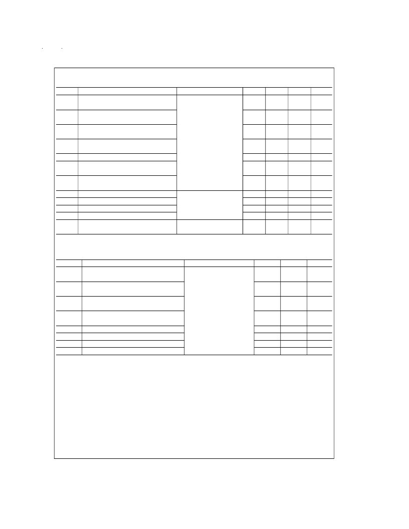
Switching Characteristics - Industrial
(Note 5) (Note 6)
Over supply voltage and -40C to +85C operating temperature range, unless otherwise specified
Sym
Parameter
t
PHLD
Differential Propagation Delay
High to Low
t
PLHD
Differential Propagation Delay
Low to High
t
SKD
Differential Skew (same
channel) |t
PHLD
t
PLHD
|
t
SK1
Skew, Pin to Pin
(same device)
t
SK2
Skew, Part to Part (Note 8)
t
TLH
Differential Transition Time
Low to High (20% to 80%)
t
THL
Differential Transition Time
High to Low (80% to 20%)
t
PHZ
Disable Time High to Z
t
PLZ
Disable Time Low to Z
t
PZH
Enable Time Z to High
t
PZL
Enable Time Z to Low
f
max
Maximum Operating
Frequency (Note 9)
Conditions
Min
6
Typ
10.5
Max
16
Units
ns
R
L
= 100
, C
L
= 50 pF
(Figures 2, 3)
6
11
16
ns
0.5
2.0
ns
1.0
2.0
ns
3.0
4.2
5.0
10
ns
ns
4.7
10
ns
(Figures 4, 5)
12
9
22
22
20
20
32
32
ns
ns
ns
ns
MHz
32
Switching Characteristics - Military
(Note 5) (Note 6)
Over supply voltage and -55C to +125C operating temperature range, unless otherwise specified
Sym
Parameter
t
PHLD
Differential Propagation Delay
High to Low
t
PLHD
Differential Propagation Delay
Low to High
t
SKD
Differential Skew (same
channel) |t
PHLD
t
PLHD
|
t
SK1
Skew, Pin to Pin
(same device)
t
PHZ
Disable Time High to Z
t
PLZ
Disable Time Low to Z
t
PZH
Enable Time Z to High
t
PZL
Enable Time Z to Low
Conditions
Min
5
Max
25
Units
ns
R
L
= 100
, C
L
= 50 pF
(Figures 2, 3)
5
25
ns
5.0
ns
5.0
ns
(Figures 4, 5)
35
35
40
40
ns
ns
ns
ns
Note 1:
“Absolute Maximum Ratings” are those values beyond which the safety of the device cannot be guaranteed. They are not meant to imply that the devices
should be operated at these limits. The table of “Electrical Characteristics” specifies conditions of device operation.
Note 2:
Current into device pins is defined as positive. Current out of device pins is defined as negative.All voltages are referenced to ground except differential volt-
ages V
OD1
, V
OD2
, V
OD3
.
Note 3:
All typicals are given for V
CC
= +3.3V, T
A
= +25C.
Note 4:
Only one output shorted at a time. The output (true or complement) is configured High.
Note 5:
f = 1 MHz, t
r
and t
f
≤
6 ns, 10% to 90%.
Note 6:
See TIA/EIA-422-B specifications for exact test conditions.
Note 7:
This specification limit is for compliance with TIA/EIA-422-B and ITU-T V.11.
Note 8:
Devices are at the same V
CC
and within 5C within the operating temperature range
Note 9:
All channels switching, output duty cycle criteria is 40%/60% measured at 50%. This parameter is guaranteed by design and characterization.
Note 10:
This parameter does not meet the TIA/EIA-422-B specification.
www.national.com
3
相关PDF资料 |
PDF描述 |
|---|---|
| DS2703 | SHA-1 Battery Pack Authentication IC |
| DS2703U | SHA-1 Battery Pack Authentication IC |
| DS2703UR | SHA-1 Battery Pack Authentication IC |
| DS2703UT | SHA-1 Battery Pack Authentication IC |
| DS2715 | NiMH Battery Pack Charge Controller |
相关代理商/技术参数 |
参数描述 |
|---|---|
| DS26LV31QML | 制造商:NSC 制造商全称:National Semiconductor 功能描述:3V Enhanced CMOS Quad Differential Line Driver |
| DS26LV31T | 制造商:NSC 制造商全称:National Semiconductor 功能描述:3V Enhanced CMOS Quad Differential Line Driver |
| DS26LV31TM | 功能描述:RS-422接口集成电路 RoHS:否 制造商:Texas Instruments 数据速率: 工作电源电压:5 V 电源电流:35 mA 工作温度范围: 安装风格:Through Hole 封装 / 箱体:PDIP-16 封装:Tube |
| DS26LV31TM/NOPB | 功能描述:RS-422接口集成电路 3V ENHANCED CMOS QUAD DIFF LINE DRVR RoHS:否 制造商:Texas Instruments 数据速率: 工作电源电压:5 V 电源电流:35 mA 工作温度范围: 安装风格:Through Hole 封装 / 箱体:PDIP-16 封装:Tube |
| DS26LV31TM/NOPB | 制造商:Texas Instruments 功能描述:RS422/485 Line Driver IC |
发布紧急采购,3分钟左右您将得到回复。