参数资料
| 型号: | DS3234S# |
| 厂商: | Maxim Integrated Products |
| 文件页数: | 6/21页 |
| 文件大小: | 0K |
| 描述: | IC RTC W/TCXO 20-SOIC |
| 产品培训模块: | Lead (SnPb) Finish for COTS Obsolescence Mitigation Program |
| 标准包装: | 45 |
| 类型: | 时钟/日历 |
| 特点: | 警报器,闰年,NVSRAM,方波输出,TCXO/晶体 |
| 存储容量: | 256B |
| 时间格式: | HH:MM:SS(12/24 小时) |
| 数据格式: | YY-MM-DD-dd |
| 接口: | SPI |
| 电源电压: | 2 V ~ 5.5 V |
| 电压 - 电源,电池: | 2 V ~ 3.8 V |
| 工作温度: | 0°C ~ 70°C |
| 安装类型: | 表面贴装 |
| 封装/外壳: | 20-SOIC(0.295",7.50mm 宽) |
| 供应商设备封装: | 20-SOIC W |
| 包装: | 管件 |
| 产品目录页面: | 1434 (CN2011-ZH PDF) |
DS3234
Extremely Accurate SPI Bus RTC with
Integrated Crystal and SRAM
14
____________________________________________________________________
Special-Purpose Registers
The DS3234 has two additional registers (control and
control/status) that control the real-time clock, alarms,
and square-wave output.
Control Register (0Eh/8Eh)
Bit 7: Enable Oscillator (EOSC). When set to logic 0,
the oscillator is started. When set to logic 1, the oscilla-
tor is stopped when the DS3234 switches to battery
power. This bit is clear (logic 0) when power is first
applied. When the DS3234 is powered by VCC, the
oscillator is always on regardless of the status of the
EOSC bit. When EOSC is disabled, all register data is
static.
Bit 6: Battery-Backed Square-Wave Enable
(BBSQW). When set to logic 1 with INTCN = 0 and VCC
< VPF, this bit enables the square wave. When BBSQW
is logic 0, the INT/SQW pin goes high impedance when
VCC < VPF. This bit is disabled (logic 0) when power is
first applied.
Bit 5: Convert Temperature (CONV). Setting this bit to
1 forces the temperature sensor to convert the temper-
ature into digital code and execute the TCXO algorithm
to update the capacitance array to the oscillator. This
can only happen when a conversion is not already in
progress. The user should check the status bit BSY
before forcing the controller to start a new TCXO exe-
cution. A user-initiated temperature conversion does
not affect the internal 64-second (default interval)
update cycle. This bit is disabled (logic 0) when power
is first applied.
A user-initiated temperature conversion does not affect
the BSY bit for approximately 2ms. The CONV bit
remains at a 1 from the time it is written until the conver-
sion is finished, at which time both CONV and BSY go
to 0. The CONV bit should be used when monitoring
the status of a user-initiated conversion.
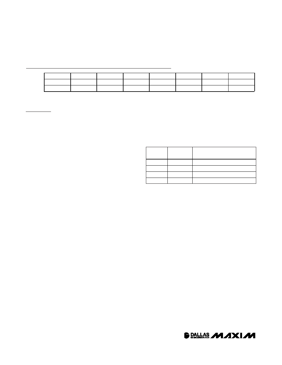
Bits 4 and 3: Rate Select (RS2 and RS1). These bits
control the frequency of the square-wave output when
the square wave has been enabled. The following table
shows the square-wave frequencies that can be select-
ed with the RS bits. These bits are both set to logic 1
(8.192kHz) when power is first applied.
Bit 2: Interrupt Control (INTCN). This bit controls the
INT/SQW signal. When the INTCN bit is set to logic 0, a
square wave is output on the INT/SQW pin. When the
INTCN bit is set to logic 1, a match between the time-
keeping registers and either of the alarm registers acti-
vates the INT/SQW (if the alarm is also enabled). The
corresponding alarm flag is always set regardless of
the state of the INTCN bit. The INTCN bit is set to logic
1 when power is first applied.
Bit 1: Alarm 2 Interrupt Enable (A2IE). When set to
logic 1, this bit permits the alarm 2 flag (A2F) bit in the
status register to assert INT/SQW (when INTCN = 1).
When the A2IE bit is set to logic 0 or INTCN is set to
logic 0, the A2F bit does not initiate an interrupt signal.
The A2IE bit is disabled (logic 0) when power is first
applied.
Bit 0: Alarm 1 Interrupt Enable (A1IE). When set to
logic 1, this bit permits the alarm 1 flag (A1F) bit in the
status register to assert INT/SQW (when INTCN = 1).
When the A1IE bit is set to logic 0 or INTCN is set to
logic 0, the A1F bit does not initiate the INT/SQW sig-
nal. The A1IE bit is disabled (logic 0) when power is
first applied.
BIT 7
BIT 6
BIT 5
BIT 4
BIT 3
BIT 2
BIT 1
BIT 0
NAME:
EOSC
BBSQW
CONV
RS2
RS1
INTCN
A2IE
A1IE
POR*:
000
111
0
RS2
RS1
SQUARE-WAVE OUTPUT
FREQUENCY
0
1Hz
0
1
1.024kHz
1
0
4.096kHz
1
8.192kHz
SQUARE-WAVE OUTPUT FREQUENCY
Control Register (0Eh/8Eh)
*
POR is defined as the first application of power to the device, either VBAT or VCC.
相关PDF资料 |
PDF描述 |
|---|---|
| DS32C35-33#T&R | IC RTC ACCURATE I2C 3.3V 20-SOIC |
| DS3911T+ | IC DAC 10BIT I2C QUAD 14TDFN |
| DS4000KI/WBGA | IC OSC TCXO 19.44MHZ 24-BGA |
| DS4026S+WCN | IC OSC TCXO 25MHZ 16-SOIC |
| DS4100HW+ | IC OSC CLOCK 100MHZ 10LCCC |
相关代理商/技术参数 |
参数描述 |
|---|---|
| DS3234S# | 功能描述:实时时钟 Integrated RTC/TCXO/Crystal RoHS:否 制造商:Microchip Technology 功能:Clock, Calendar. Alarm RTC 总线接口:I2C 日期格式:DW:DM:M:Y 时间格式:HH:MM:SS RTC 存储容量:64 B 电源电压-最大:5.5 V 电源电压-最小:1.8 V 最大工作温度:+ 85 C 最小工作温度: 安装风格:Through Hole 封装 / 箱体:PDIP-8 封装:Tube |
| DS3234S# | 制造商:Maxim Integrated Products 功能描述:RTC TCXO CRYSTAL 3.3V 20SOIC 制造商:Maxim Integrated Products 功能描述:RTC, TCXO, CRYSTAL, 3.3V, 20SOIC 制造商:Maxim Integrated Products 功能描述:RTC, TCXO, CRYSTAL, 3.3V, 20SOIC; Date Format:DD:MM:YYYY; Clock Format:HH:MM:SS; Clock IC Type:RTC; Supply Voltage Min:2V; Supply Voltage Max:5.5V; Digital IC Case Style:SOIC; No. of Pins:20; Interface Type:SPI; Operating Temperature;RoHS Compliant: Yes |
| DS3234S#T&R | 制造商:Maxim Integrated Products 功能描述:REAL TIME CLOCK SERL 256BYTE 20SOIC W - Tape and Reel 制造商:Maxim Integrated Products 功能描述:IC RTC W/TCXO 20-SOIC |
| DS3234S#T&R | 功能描述:实时时钟 Integrated RTC/TCXO/Crystal RoHS:否 制造商:Microchip Technology 功能:Clock, Calendar. Alarm RTC 总线接口:I2C 日期格式:DW:DM:M:Y 时间格式:HH:MM:SS RTC 存储容量:64 B 电源电压-最大:5.5 V 电源电压-最小:1.8 V 最大工作温度:+ 85 C 最小工作温度: 安装风格:Through Hole 封装 / 箱体:PDIP-8 封装:Tube |
| DS3234S+ | 功能描述:实时时钟 RoHS:否 制造商:Microchip Technology 功能:Clock, Calendar. Alarm RTC 总线接口:I2C 日期格式:DW:DM:M:Y 时间格式:HH:MM:SS RTC 存储容量:64 B 电源电压-最大:5.5 V 电源电压-最小:1.8 V 最大工作温度:+ 85 C 最小工作温度: 安装风格:Through Hole 封装 / 箱体:PDIP-8 封装:Tube |
发布紧急采购,3分钟左右您将得到回复。