参数资料
| 型号: | DS32508N# |
| 厂商: | Maxim Integrated Products |
| 文件页数: | 68/130页 |
| 文件大小: | 0K |
| 描述: | IC LIU DS3/E3/STS-1 484-BGA |
| 产品培训模块: | Lead (SnPb) Finish for COTS Obsolescence Mitigation Program |
| 标准包装: | 60 |
| 类型: | 线路接口装置(LIU) |
| 规程: | IEEE 1149.1 |
| 电源电压: | 1.8V, 3.3V |
| 安装类型: | 表面贴装 |
| 封装/外壳: | 484-BGA |
| 供应商设备封装: | 484-BGA(23x23) |
| 包装: | 管件 |
第1页第2页第3页第4页第5页第6页第7页第8页第9页第10页第11页第12页第13页第14页第15页第16页第17页第18页第19页第20页第21页第22页第23页第24页第25页第26页第27页第28页第29页第30页第31页第32页第33页第34页第35页第36页第37页第38页第39页第40页第41页第42页第43页第44页第45页第46页第47页第48页第49页第50页第51页第52页第53页第54页第55页第56页第57页第58页第59页第60页第61页第62页第63页第64页第65页第66页第67页当前第68页第69页第70页第71页第72页第73页第74页第75页第76页第77页第78页第79页第80页第81页第82页第83页第84页第85页第86页第87页第88页第89页第90页第91页第92页第93页第94页第95页第96页第97页第98页第99页第100页第101页第102页第103页第104页第105页第106页第107页第108页第109页第110页第111页第112页第113页第114页第115页第116页第117页第118页第119页第120页第121页第122页第123页第124页第125页第126页第127页第128页第129页第130页
DS32506/DS32508/DS32512
42 of 130
8.7.3 General-Purpose I/O Pins
When a microprocessor interface is enabled (IFSEL
≠ 000), there are two general-purpose I/O (GPIO) pins
available per port, each of which can be used as a general-purpose input, general-purpose output, or loss-of-signal
output. In addition, GPIOB1, GPIOB2, and GPIOB3 can be used as a global I/O signal. The GPIO pins are
independently configurable using the GPIOynS fields of the GLOBAL.GIOACR and GLOBAL.GIOBCR registers
(see Table 8-15). When a GPIO pin is configured as an input, its value can be read from the GLOBAL.GIOARR or
GLOBAL.GIOBRR registers. When a GPIO pins is configured as a loss-of-signal status output, its state mimics the
state of the LINE.RSR:LOS status bit. When a port is powered down and a GPIO pin has been programmed as an
associated loss-of-signal output, the pin is held low. Programming a GPIO pin as a global signal overrides the I/O
settings specified by the GPIOynS field for that pin and configures the pin as an input or an output as shown in
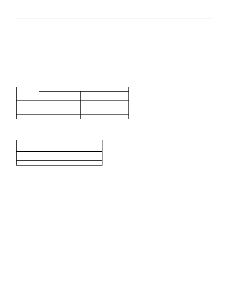
Table 8-14. GPIO Pin Global Signal Assignments
GLOBAL SIGNAL
PIN
FUNCTION
CONTROL BIT
GPIOAn
None
—
GPIOB1
Global PMU input
GLOBAL.CR1.GPM[1:0]
GPIOB2
Global TMEI input
GLOBAL.CR1.MEIMS
GPIOB3
1SREF output
GLOBAL.CR1.G1SROE
GPIOBk
None
—
Note:
n = 1 to 12, k = 4 to 12.
Table 8-15. GPIO Pin Control
GPIOynS[1:0]
FUNCTION
00
Input
01
Output LOS status for port n
10
Output logic 0
11
Output logic 1
Note:
n = 1 to 12, y = A or B.
8.7.4 Performance Monitor Register Update
Each performance monitor counter can count at least one second of events before saturating at the maximum
count. Each counter has an associated status bit that is set when the counter value is not zero, a latched status bit
that is set when the counter value changes from zero to one, and a latched status bit that is set each time the
counter is incremented.
There is a holding register for each performance monitor counter that is updated when a performance monitoring
update is performed. A performance monitoring update causes the counter value to be loaded into the holding
register and the counter to be cleared. If a counter increment occurs at the exact same time as the counter reset,
the counter is loaded with a value of one, and the “counter is non-zero” latched status bit is set.
The performance monitor update (PMU) signal initiates a performance monitoring update. The PMU signal can be
sourced from a general-purpose I/O pin (GPIOB1), the internal one-second reference, a global register bit
(GLOBAL.CR1:GPMU), or a port register bit (PORT.CR1:PMU). Note: The BERT PMU can be sourced from a
block level register bit (BERT.CR:LPMU). To use GPIOB1, GLOBAL.CR1.GPM[1:0] is set to 01, the appropriate
PORT.CR1:PMUM bits are set to 1, and the appropriate BERT.CR:PMUM bits are set to 1. To use the internal one-
second reference, GLOBAL.CR1:GPM[1:0] is set to 1X, the appropriate PORT.CR1:PMUM bits are set to 1, and
the appropriate BERT.CR:PMUM bits are set to 1. To use the global PMU register bit, GLOBAL.CR1:GPM[1:0] is
set to 00, the appropriate PORT.CR1:PMUM bits are set to 1, and the appropriate BERT.CR:PMUM bits are set to
1. To use the port PMU register bit, the associated PORT.CR1:PMUM bit is set to 0, and the appropriate
BERT.CR:PMUM bits are set to 1. To use the BERT.CR:LPMU register bit, the appropriate BERT.CR:PMUM bit is
set to 0.
When using the global or port PMU register bits, the PMU bit should be set to initiate the process and cleared when
the associated PMS status bit (GLOBAL.SR:GPMS or PORT.SR:PMS) is set. When using the GPIO pin or internal
one-second reference, the PMS bit is set shortly after the signal goes high, and cleared shortly after the signal
相关PDF资料 |
PDF描述 |
|---|---|
| M83723/71W10207 | CONN RCPT 2POS WALL MT W/SCKT |
| VI-21M-IW-B1 | CONVERTER MOD DC/DC 10V 100W |
| VI-26V-IU-F1 | CONVERTER MOD DC/DC 5.8V 200W |
| MAX1139LEEE+T | IC ADC 10BIT SERIAL 16-QSOP |
| VI-B1R-IV-B1 | CONVERTER MOD DC/DC 7.5V 150W |
相关代理商/技术参数 |
参数描述 |
|---|---|
| DS32508N# | 功能描述:网络控制器与处理器 IC 8-Port DS3/E3/STS-1 Line Interface Unit RoHS:否 制造商:Micrel 产品:Controller Area Network (CAN) 收发器数量: 数据速率: 电源电流(最大值):595 mA 最大工作温度:+ 85 C 安装风格:SMD/SMT 封装 / 箱体:PBGA-400 封装:Tray |
| DS32508N+ | 功能描述:网络控制器与处理器 IC 8-Port DS3/E3/STS-1 Line Interface Unit RoHS:否 制造商:Micrel 产品:Controller Area Network (CAN) 收发器数量: 数据速率: 电源电流(最大值):595 mA 最大工作温度:+ 85 C 安装风格:SMD/SMT 封装 / 箱体:PBGA-400 封装:Tray |
| DS32508NA2 | 制造商:Maxim Integrated Products 功能描述:DS32508NA2 X8 DS3/E3 LIU - Rail/Tube |
| DS32508N-W | 功能描述:网络控制器与处理器 IC RoHS:否 制造商:Micrel 产品:Controller Area Network (CAN) 收发器数量: 数据速率: 电源电流(最大值):595 mA 最大工作温度:+ 85 C 安装风格:SMD/SMT 封装 / 箱体:PBGA-400 封装:Tray |
| DS32508-W | 功能描述:网络控制器与处理器 IC RoHS:否 制造商:Micrel 产品:Controller Area Network (CAN) 收发器数量: 数据速率: 电源电流(最大值):595 mA 最大工作温度:+ 85 C 安装风格:SMD/SMT 封装 / 箱体:PBGA-400 封装:Tray |
发布紧急采购,3分钟左右您将得到回复。