- 您现在的位置:买卖IC网 > PDF目录223667 > DSC-10510-193 (DATA DEVICE CORP) DIGITAL TO SYNCHRO OR RESOLVER, DMA40 PDF资料下载
参数资料
| 型号: | DSC-10510-193 |
| 厂商: | DATA DEVICE CORP |
| 元件分类: | 位置变换器 |
| 英文描述: | DIGITAL TO SYNCHRO OR RESOLVER, DMA40 |
| 封装: | TDIP-40 |
| 文件页数: | 9/14页 |
| 文件大小: | 202K |
| 代理商: | DSC-10510-193 |
4
Data Device Corporation
www.ddc-web.com
DSC-10510
M-04/06-0
INTRODUCTION
SYSTEM CONSIDERATIONS:
POWER SURGE AT TURN ON
The output power stages can fully turn on before all the supplies
stabilize, when power is initially applied. Multiple D/S converters
with substantial loads can cause the system power supply to
have difficulty coming up and may even cause the supply to shut
down. It is important that the power supply can handle the turn-
on surge or that the D/S turn-ons be staggered. Typically, the
surge will be twice the max rated draw of the converter.
POWER SUPPLY CYCLING
Power supply cycling of the DSC-10510 should follow the guide-
lines below to avoid any potential problems.
Strictly maintain proper sequencing of supplies and signals per
typical CMOS circuit guidelines:
- Apply power supplies first (+15, -15V and ground).
- Apply digital control signals next.
- Apply analog signals last.
The reverse sequence should be followed during power down of
the circuit.
It is also recommended that the KICK pin, if unused, be left in the
“No Connection” (N/C) state. The internal pull up will disable the
pin (this removes any unnecessary voltages from the converter).
TORQUE LOAD MANAGEMENT
The above problems are compounded by the high power levels
involved when multiple torque loads (TR) are being driven. In this
configuration, power supply fold back problems are common
unless the stagger technique is used. The load will also need
time to stabilize. On turn-on it is likely that some of output loads
will be at a different angle than the D/S output. As the angular dif-
ference increases so does the power draw until the difference is
180 degrees. At this point the load impedance drops to Zss and
current draw is at a maximum.
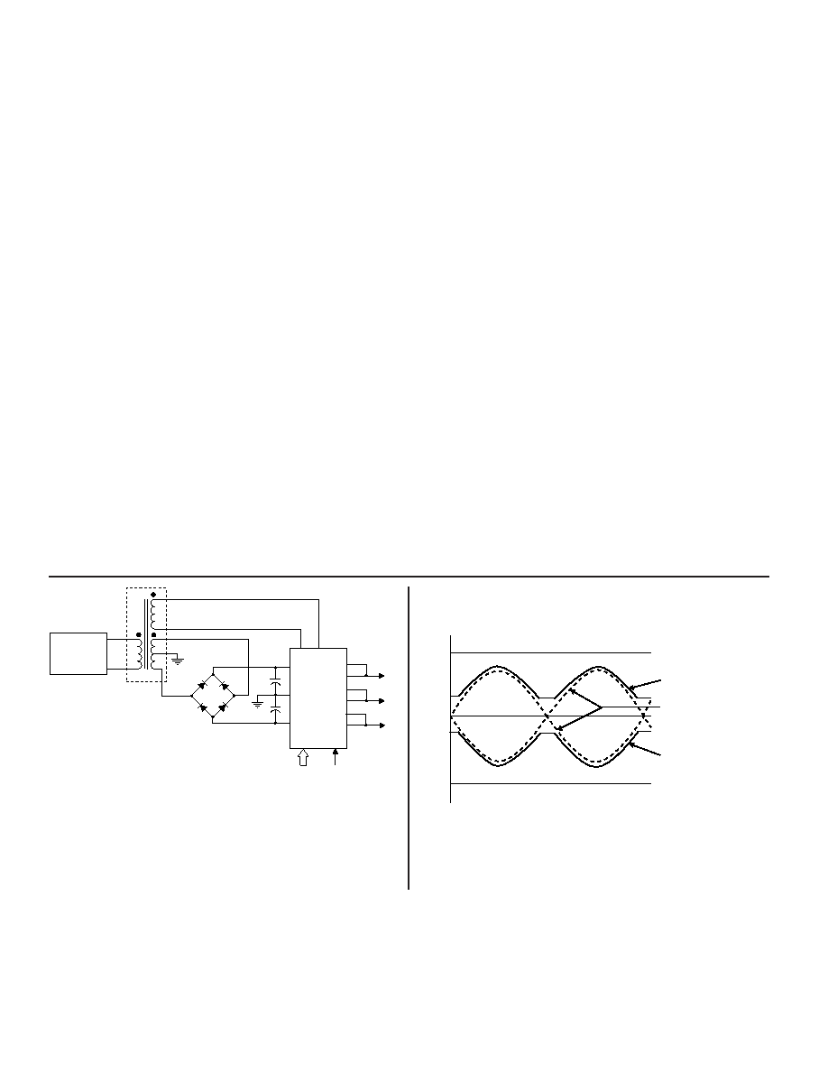
PULSATING POWER SUPPLIES
D/S and D/R converters have been designed to operate their out-
put power stages with pulsating power to reduce power dissipa-
tion and power demand from regulated supplies. Figures 2 and 3
illustrate this technique. The power output stage is only supplied
with enough instantaneous voltage to be able to drive the
required instantaneous signal level. The AC reference can be full
wave rectified and applied to the push-pull output drivers since
the output signal is required to be in phase with the AC refer-
ence. The supply voltage will be just a few volts more than the
output signal and internal power dissipation is minimized.
REFERENCE
SOURCE
26V rms 400Hz
1
2
3
4
5
6
7
3.4V rms
21.6V rms
C.T.
D1
D2
D3
D4
C1
C2
+
RL'
RH'
+V
GND
-V
S1
S2
S3
DIGITAL
INPUT
±15VDC
DSC10510
S1
S1'
S2
S2'
S3
S3'
T1
42359
NOTES:
PARTS LIST FOR 400Hz
D1, D2, D3, D4 = 1N4245
C1 AND C2 = 47F, 35V DC CAPACITOR
See Figure 14
FIGURE 2. TYPICAL CONNECTION DIAGRAM
UTILIZING PULSATING POWER SOURCE
FIGURE 3. PULSATING POWER SUPPLY VOLTAGE
WAVEFORMS
+v
- v
+DC SUPPLY LEVEL
-DC SUPPLY LEVEL
POSITIVE PULSATING
SUPPLY VOLTAGE
NEGATIVE PULSATING
SUPPLY VOLTAGE
AMPLIFIER OUTPUT
VOLTAGE ENVELOPE
相关PDF资料 |
PDF描述 |
|---|---|
| DSC-10510-163S | DIGITAL TO SYNCHRO OR RESOLVER, DMA40 |
| DSC5031-29HB | DIGITAL TO SYNCHRO OR RESOLVER, XMA26 |
| DSC5131-249SS | DIGITAL TO SYNCHRO OR RESOLVER, XMA26 |
| DSLU304 | DC-DC REG PWR SUPPLY MODULE |
| DSLU325 | DC-DC REG PWR SUPPLY MODULE |
相关代理商/技术参数 |
参数描述 |
|---|---|
| DSC-10510-193L | 制造商:未知厂家 制造商全称:未知厂家 功能描述:Converter |
| DSC-10510-193Q | 制造商:未知厂家 制造商全称:未知厂家 功能描述:Converter |
| DSC-10510-193S | 制造商:未知厂家 制造商全称:未知厂家 功能描述:Converter |
| DSC-10510-194 | 制造商:未知厂家 制造商全称:未知厂家 功能描述:Converter |
| DSC-10510-194L | 制造商:未知厂家 制造商全称:未知厂家 功能描述:Converter |
发布紧急采购,3分钟左右您将得到回复。