- 您现在的位置:买卖IC网 > PDF目录381738 > DVP04DA-P (Delta Electronics, Inc.) Analog Input Module Instruction Sheet PDF资料下载
参数资料
| 型号: | DVP04DA-P |
| 厂商: | Delta Electronics, Inc. |
| 英文描述: | Analog Input Module Instruction Sheet |
| 中文描述: | 模拟输入模块教学片 |
| 文件页数: | 2/2页 |
| 文件大小: | 470K |
| 代理商: | DVP04DA-P |
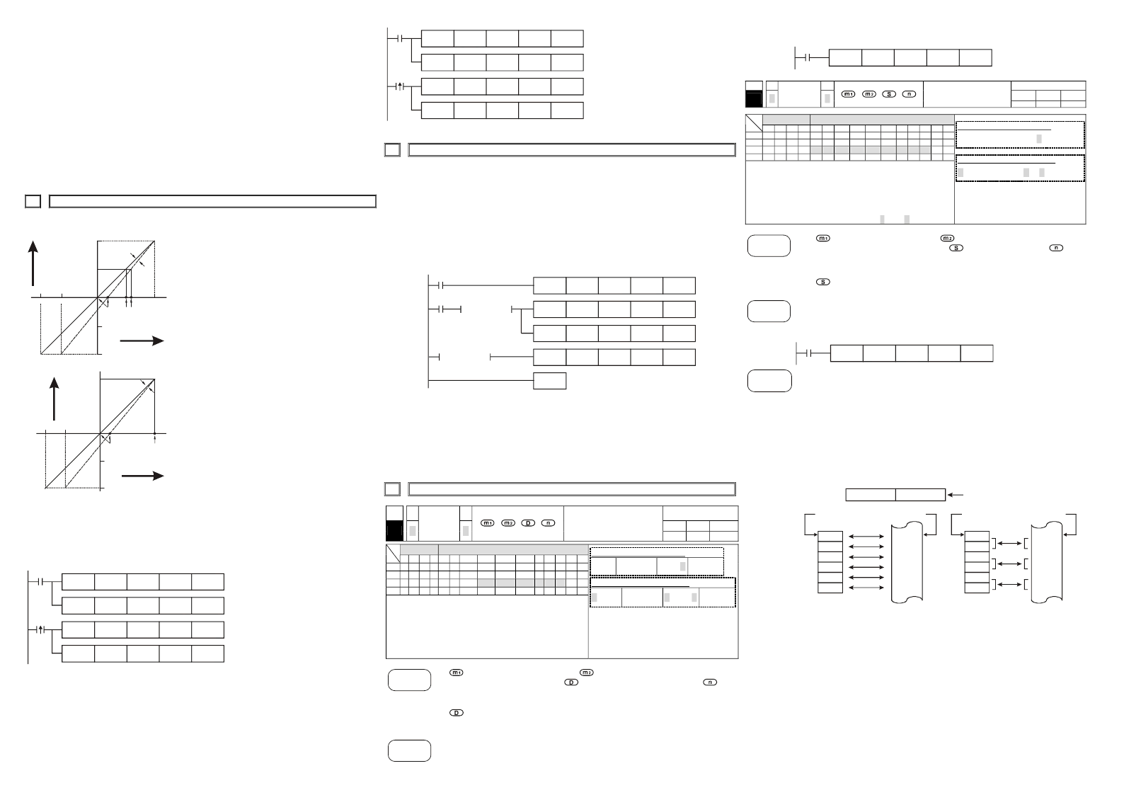
10. CR#31: it is used to set RS-485 communication address. Setting range is 01~255 and factory
setting is K1.
11. CR#32 is used to set RS-485 communication baud rate: 4800, 9600, 19200, 38400, 57600,
115200 bps. b0: 4800bps. b1: 9600bps. (factory setting) b2: 19200bps. b3: 38400 bps. b4:
57600 bps. b5: 115200 bps. b6-b13: reserved. b14: exchange low and high byte of CRC
check code. (only for RTU mode) b15=0: ASCII mode. b15=1: RTU mode. Communication
format: ASCII mode is 7Bit, even bit, 1 stop bit (7 E 1). Communication format of RTU mode
is 8Bit, even bit, 1 stop bit (8 E 1).
12. CR#33 is used to set the internal function priority, such as characteristic register.
Output
latched function will save output setting in the inner memory before power loss.
13. CR#34: software version.
14. CR#35~ CR#48: system used.
15. The corresponding parameters address H4000~H4030 of CR#0~CR#48 are provided for user to
read/write data through RS-485.
A.
Communication baud rate: 4800, 9600, 19200, 38400, 57600, 115200 bps.
B.
Communication format: ASCII mode is 7Bit, even bit, 1 stop bit (7 E 1). Communication
format of RTU mode is 8Bit, even bit, 1 stop bit (8 E 1).
C.
Function code: 03H—read data from register. 06H—write one WORD into register.
10H—write multiple WORD into registers.
5
ADJUST A/D CONVERSION CHARACTERISTIC CURVE
5.1 Adjust A/D Conversion Characteristic Curve
Voltage input mode
Mode 0 of CR#1 GAIN=5V (4000
LSB
),
OFFSET=0V (0
LSB
)
Mode 1 of CR#1 GAIN=6V (4800
LSB
),
OFFSET=2V (1600
LSB
)
GAIN:
Voltage input value when digital
output is 4000. Setting range is
-4V~+20V (-3200
LSB
~ +16000
LSB
)
OFFSET:
Voltage input value when digital
output is 0.
Setting range: -5V~+5V (-4000
LSB
~
+4000
LSB
)
GAIN
-
OFFSET: Setting range is +1V~+15V
(+800
LSB
~ +12000
LSB
)
+8000
+4000
-4000
10V
-8000
-6V
-10V
6V
5V
2V
0
GAIN
OFFSET
Digital
output
Voltage input
mode 0
mode 1
Current input mode:
Mode 2 of CR#1 GAIN = 20mA (4000
LSB
),
OFFSET=4mA (800
LSB
).
Mode 3 of CR#1 GAIN = 20mA (4000
LSB
),
OFFSET=0mA (0
LSB
).
GAIN:
Current input value when digital
output is +4000. Setting range is -20
mA~+20 mA (-4000
LSB
~ +4000
LSB
)
OFFSET:
Current input value when digital
output value is 0. Setting range is-16
mA ~+52 mA (-3200
LSB
~ +10400
LSB
)
GAIN
-
OFFSET: Setting range is +4mA ~ +32mA
(800
LSB
~ +6400
LSB
)
+4000
-4000
-12mA
-20mA
4mA
0
OFFSET
20mA
GAIN
Digital
output
current input
mode 3
mode 2
Using charts above to adjust A/D conversion characteristic curve of voltage input mode and
current input mode. Users can adjust conversion characteristic curve by changing OFFSET values
(CR#18~CR#21) and GAIN values (CR#24~CR#27) depend on application.
LSB(Least Significant Bit): 1. voltage input: 1
LSB
=10V/8000=1.25mV. 2. current input:
1
LSB
=20mA/4000=5μA.
5.2. Program Example for Adjusting A/D Conversion Characteristics Curve
Example 1: setting OFFSET value of CH1 to 0V(=K0
LSB
) and GAIN value of CH1 to 2.5V(=K2000
LSB
).
X0
K2000
K24
H0
K1
K0
K1
H0
K1
M1002
K0
K33
K1
K0
K1
K18
K0
K0
TO
TO
TO
TO
z
Writing H0 to CR#1 of analog
input module no. 0 and set CH1
to
mode
0
-10V~+10V)
z
Writing H1 to CR#33 and allow to
adjust characters of CH1~CH4.
z
When X0 switches from Off to
On, K0
LSB
of
OFFSET value will
be wrote in CR#18 and K2000
LSB
of GAIN value will be wrote in
CR#24.
(voltage
input
Example 2: setting OFFSET value of CH2 to 2mA(=K400
LSB
) and GAIN value of CH2 to 18 mA
(=K3600
LSB
)
X0
K1
K0
K1
H0
K1
M1002
K0
K33
K1
K0
K1
K0
H18
K19
K25
K400
K3600
TO
TO
TO
TO
z
Writing H18 to CR#1 of analog
input mode no. 0 and set CH2 to
mode 3 (current input: -20 mA ~
+20mA)
z
Writing H0 to CR#33 and allow to
adjust characteristics of CH4.
z
When X0 switches from Off to
On, K400
LSB
of
OFFSET value will
be wrote in CR#19 and K3600
LSB
of GAIN value will be wrote in
CR#25.
6
INITIAL PLC START-UP
Lamp display:
1.
2.
When power is on, POWER LED will be lit and ERROR LED will be lit for 0.5 second.
Normal run: POWER LED should be lit and ERROR LED should turn off. When power
supply is lower than 19.5V, ERROR LED will blink continuously till the power supply goes
higher than 19.5V.
When it connects to PLC MPU in series, RUN LED on MPU will be lit and A/D LED or D/A
LED should blink.
After receiving the first RS-485 instruction during controlling by RS-485, A/D LED or D/A
LED should blink.
After converting, ERROR LED should blink if input or output exceeds upper bound or lower
than lower bound.
Example:
M1000
FROM
3.
4.
5.
K1
K0
K1
K1
K0
K0
K0
TO
END
K2
K6
D0
H3030
K32
D20
K4
FROM
TO
K0
K2
= H400 D0
M1002
= H400 D0
Explanation:
z
Read the data of model type from extension module K0 and distinguish if the data is H400
(DVP04AD-H model type).
z
If the model type is DVP04AD-H, M11 is on and the setting input mode is (CH1, CH3)= mode 0,
(CH2, CH4)= mode 3.
z
Set the number of times for average of CH1 and CH2 are K32.
z
Read the input signal average value of CH1~CH4 (4 data) and saved into D20~D23.
7
RELATED INSTRUCTIONS EXPLANATION
API
78
D
FROM
Bit device
X Y M S K H KnX KnY KnM KnS T C D E F
m
1
m
2
D
n
y
Note: The usage range of operand m
1
is 0~7.
The usage range of operand m
2
: ES/EP:
0-48, EH: 0-254.
The usage range of operand n: ES/EP: n=
1~(49-m2), EH: 1~(255-m2).
ES series model doesn’t support pulse
execution instruction (FROMP, DFROMP).
: the number for special module.
special module that will be read.
data number of reading one time.
DVP-series PLC uses this instruction to read CR data of special module.
: When assigning bit operand, K1~K4 are used for 16-bit and K5~K8 are used
for 32-bit.
Please refer the footnote below for the calculation of special module number.
To read the content of CR#24 of special module#0 to D0 of PLC and to read the
content of CR#25 of special module#0 to D1 of PLC. It can read 2 data in one time
(n=2).
Applicable model
ES
EP
9
9
EH
9
P
Read special module
CR data
16-bit instruction (9 STEPS)
FROMexecution
32-bit instruction (17 STEPS)
DFROMexecution
y
Flag: When M1083=On, it allows to
insert interrupt during
FROM/TO.
Refer to following for detail.
Word device
FROMPexecution
DFROMPexecution
Command
Explanation
: the number of CR (Control Register) of
: the location to save reading data.
: the
Program
Example
The instruction will be executed when X0=On. The instruction won’t be executed
when X0=Off and the content of previous reading data won’t change.
X0
FROM
K0
K24
D0
K2
API
79
Applicable model
ES
EP
9
9
EH
9
D
TO
P
Special module CR
data write in
Bit device
X
Y
Word device
M
S
K
H KnX KnY KnM KnS T
C
D
E
F
m
1
m
2
S
n
y
Note: The usage range of operand m
1
is 0~7.
The usage range of operand m
2
: ES/EP: 0-48,
EH: 0-254.
The usage range of operand n: ES/EP: n=
1~(49-m2), EH: 1~(255-m2).
For ES series, it doesn’t support pulse
execution instruction (TOP, DTOP)
16-bit instruction (9 STEPS)
Continuous
execution
TO
TOP
Pulse
execution
32-bit instruction (17 STEPS)
DTOexecution
y
Flag: When M1083=On, it allows
to insert interrupt during
FROM/TO.
Refer to following for detail.
DTOPexecution
Command
Explanation
: the number of special module.
of special module that will be wrote in.
data number to write in one time.
DVP-series PLC uses this instruction to write data into CR of special module.
: the number of CR (Control Register)
: the data to write in CR.
: the
: When assigning bit operand, K1~K4 can be used for 16-bit and K5~K8 can
be used for 32-bit.
Using 32-bit instruction DTO, program will write D11 and D10 into CR#3 and
CR#2 of special module#0. It only writes a group of data in one time (n=1).
The instruction will be executed when X0=On and it won’t be executed when
X0=Off. The data that wrote in previous won’t have any change.
X0
K0
K2
D0
DTO
Program
Example
K1
Footnote
The rule of instruction operand:
m1: arrangement number of special module. The number of special module
that connects to PLC MPU. The numbering order of special module from the
near to the distant of MPU is from 0 to 7. The maximum is 8 special modules
and won’t occupy I/O point.
m2: the number of CR. Built in 16-bit of 49 groups memory of special module
is called CR (Control Register). The number of CR uses decimal digital
(#0~#48). All running status and setting values of special module has
included.
If using FROM/TO instruction, the unit of read/write of CR is one number for
one time. If using DFROM/DTO instruction, the unit of read/write of CR is two
numbers in one time.
Upper 16-bit Lower 16-bit
CR #10
CR #9
Specified CR number
(Access16-bit if n=2, or 32-bit if n=1. Same controlled registers are accessed).
Specified device
Specified CR
D0
D1
D2
D3
D4
D5
CR #5
CR #6
CR #7
CR #8
CR #9
CR #10
D0
D1
D2
D3
D4
D5
CR #5
CR #6
CR #7
CR #8
CR #9
CR #10
Specified device Specified CR
16-bit command when n=6
In ES series models, flag M1083 is not provided. When FROM/TO instruction is
executed, all interrupts (including external or internal interrupt subroutines) will be
disabled. All interrupts will be executed after completing FROM/TO instruction.
Besides, FROM/TO instruction also can be executed in the interrupt subroutine.
The function of the flag M1083 (FROM/TO mode exchange) provided in EP/EH
series models:
a.
When M1083=Off, all interrupts (including external or internal interrupt
subroutines) will be disabled when FROM/TO instruction is executed. The
Interrupts will resumed after FROM/TO instruction complete. Please be
advised FROM/TO instruction can be executed in the interrupt subroutine.
b.
When M1083=On, if an interrupt enable occurs while FROM/TO
instruction are executing, the interrupt FROM/TO instruction will be
blocked till the requested interrupt finish. Unlike M1080 off situation,
FROM/TO instruction cannot be executed in the interrupt subroutine.
32-bit command when n=3
相关PDF资料 |
PDF描述 |
|---|---|
| DVP04DA-S | Analog Input Module Instruction Sheet |
| DVP04AD-H | Analog Input Module Instruction Sheet |
| DVP04AD-P | Analog Input Module Instruction Sheet |
| DVP04AD-S | Analog Input Module Instruction Sheet |
| DVP04TC-H | Analog Input Module Instruction Sheet |
相关代理商/技术参数 |
参数描述 |
|---|---|
| DVP04DA-S | 制造商:DELTA 制造商全称:Delta Electronics, Inc. 功能描述:Analog Input Module Instruction Sheet |
| DVP04PT-H | 制造商:DELTA 制造商全称:Delta Electronics, Inc. 功能描述:Analog Input Module Instruction Sheet |
| DVP04PT-H2 | 制造商:Delta Electronics Inc 功能描述: |
| DVP04PT-P | 制造商:DELTA 制造商全称:Delta Electronics, Inc. 功能描述:Analog Input Module Instruction Sheet |
| DVP04PT-S | 制造商:Delta Electronics Inc 功能描述: |
发布紧急采购,3分钟左右您将得到回复。