- 您现在的位置:买卖IC网 > PDF目录97407 > ECN3036F MOTOR CONTROLLER PDF资料下载
参数资料
| 型号: | ECN3036F |
| 英文描述: | MOTOR CONTROLLER |
| 中文描述: | 电机控制器 |
| 文件页数: | 5/9页 |
| 文件大小: | 82K |
| 代理商: | ECN3036F |
PDE-3021-0
ECN3021
5.3
PWM Operation
The PWM signal is produced by comparing the input voltage at VSP terminal with the voltage from the
internal SAW wave. The duty of the PWM signal can be changed by the triangular wave amplitude level,
from the minimum point of VSAWL to the maximum point of VSAWH, and when the level is under
VSAWL, the duty becomes 0%, and when the level is over VSAWH, the duty becomes 100%. In addition,
chopping with the PWM signal is operated in the bottom arm circuit.
5.4
Over Current Limiting Operation
This IC detects over current by checking the voltage drop at the external resistance RS. When the input
voltage at RS terminal exceeds the internal reference voltage(Vref), this IC turns off the output of the bottom
arm circuit. After over current detection, reset operation is done at every period of the inner clock signal
(VTR terminal).
5.5
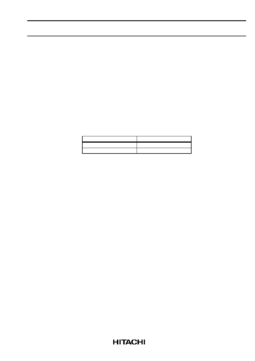
Rotating Direction Sense Operation
The rotation direction of the motor is detected by the signal at DM terminal. Table 1 shows the output signal
for the rotation direction.
Table 1.
Output signal for the rotation direction
Rotating Direction
Output (DM terminal)
U-V-W
L
U-W-V
H
5.6
Vcc under voltrage Detection
When
Vcc supply voltage becomes below LVSDON(11.5V typ),
all of the IGBTs shut off.
This condition is recovered
when Vcc supply voltage becomes greater than LVSDOFF(12.0V typ).
相关PDF资料 |
PDF描述 |
|---|---|
| ECOFLEX | |
| ECS1X5-1.0 | Peripheral IC |
| ESC3X10 | Peripheral IC |
| ESC3X9 | Peripheral IC |
| ECS1X5 | Peripheral IC |
相关代理商/技术参数 |
参数描述 |
|---|---|
| ECN3053F | 制造商:HITACHI 制造商全称:Hitachi Semiconductor 功能描述:Single chip driver IC |
| ECN30601 | 制造商:HITACHI 制造商全称:Hitachi Semiconductor 功能描述:HIGH-VOLTAGE MONOLITHIC IC |
| ECN30601SP | 制造商:HITACHI 制造商全称:Hitachi Semiconductor 功能描述:HIGH-VOLTAGE MONOLITHIC IC |
| ECN30601SPR | 制造商:HITACHI 制造商全称:Hitachi Semiconductor 功能描述:HIGH-VOLTAGE MONOLITHIC IC |
| ECN30601SPV | 制造商:HITACHI 制造商全称:Hitachi Semiconductor 功能描述:HIGH-VOLTAGE MONOLITHIC IC |
发布紧急采购,3分钟左右您将得到回复。